
A kind of thermal decomposition preparation method of thin film
A thin film preparation and thermal decomposition technology, applied in metal material coating process, coating, gaseous chemical plating, etc., can solve the problems of increased equipment complexity, failure rate, expensive equipment, and high equipment requirements, and achieve significant technological progress , obvious substantive characteristics, the effect of improving the quality of film formation
Patent Information
- Authority / Receiving Office
- CN · China
- Patent Type
- Patents(China)
- Current Assignee / Owner
- Publication Date
- 2020-03-31
Smart Images
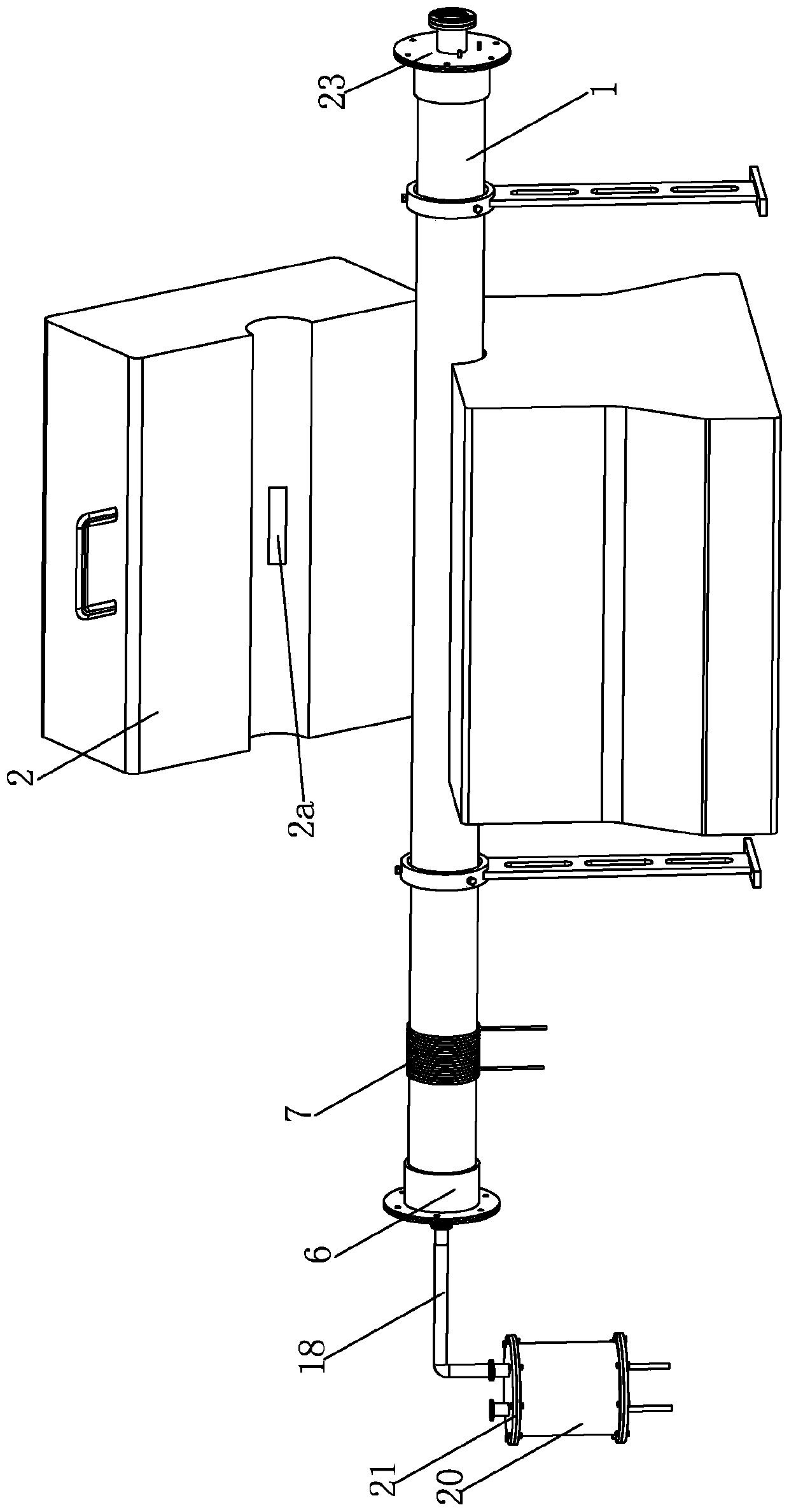
Figure 1 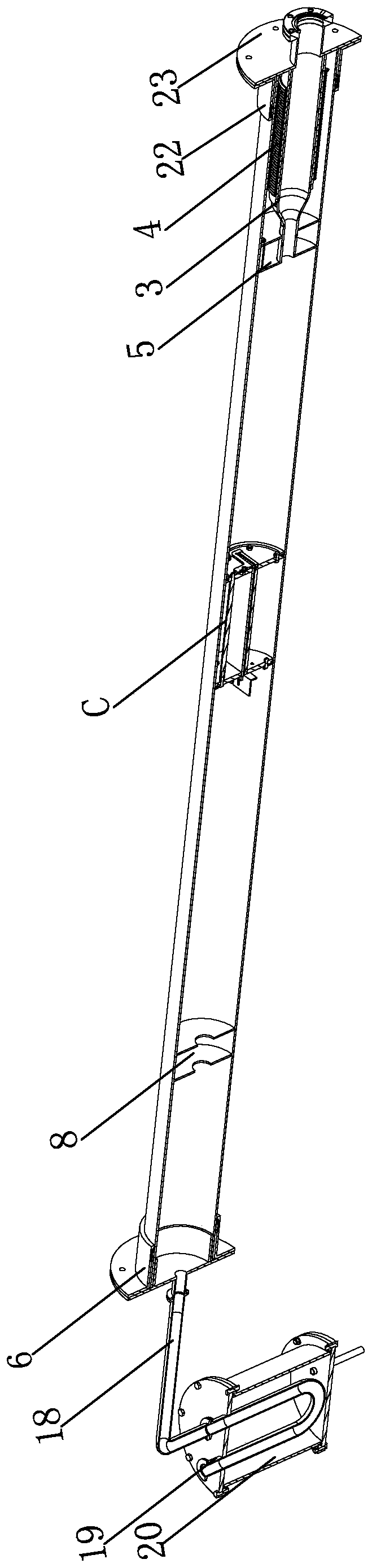
Figure 2 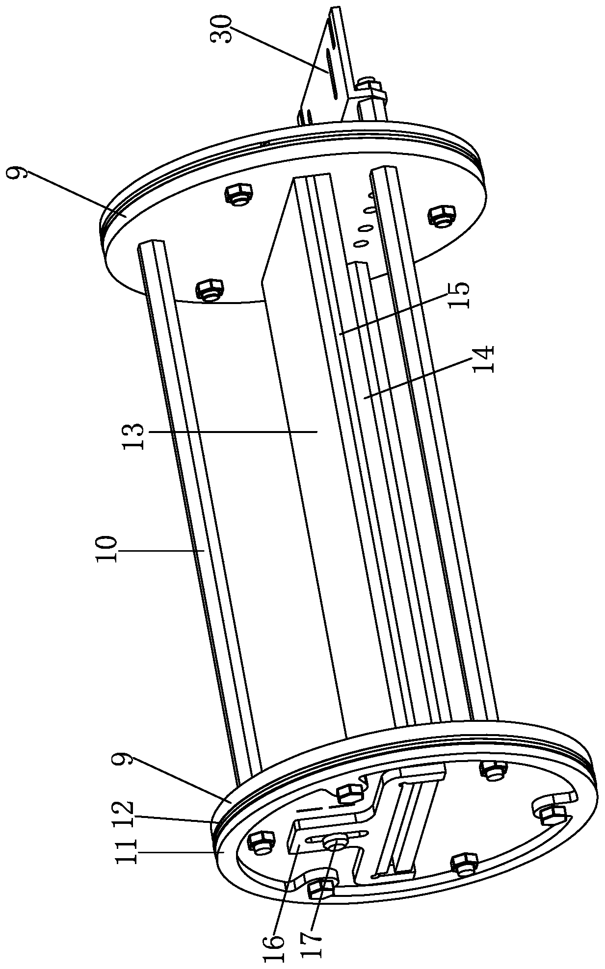
Figure 3
Abstract
Description
technical field
[0001] The invention belongs to the field of film preparation, in particular to a method for preparing a film by thermal decomposition. Background technique
[0002] In industrial production, it is often necessary to coat the surface of the substrate. The existing thin film preparation process mainly adopts thermal decomposition method. One thermal decomposition method uses a tube furnace to heat the substrate in the quartz tube. The substrate is arranged parallel or inclined along the axis of the quartz tube so that the precursor aerosol Species undergo pyrolysis reactions near the surface of the substrate, thereby attaching a thin film to the surface of the substrate. In addition, the thermal decomposition reaction is carried out under normal pressure or low pressure and vacuum environment.
[0003] The defects of the existing thermal decomposition process are as follows: 1. We find that the existing thermal decomposition process cannot produce high-quali...
Examples
Embodiment Construction
[0023] Below in conjunction with accompanying drawing and embodiment the present invention will be further described:
[0024] A method for preparing a thin film by thermal decomposition, characterized in that it comprises the following steps:
[0025] Step a: Design a thin film preparation equipment, such as figure 1 - As shown in 3, the thin film preparation equipment mainly includes quartz tube 1, tube furnace 2, compression tube 3, internal cooling tube 4 and first heat resistance plate 5 and so on. Wherein, the pyrolysis part of the quartz tube 1 is located in the furnace cavity of the tube furnace 2, which is an outsourced part for heating the quartz tube. In this case, a light-loading hole 2a is opened on the furnace cover of the tube furnace 2, and the light-loading hole 2a runs through the top and bottom surfaces of the furnace cover, and the light-loading hole 2a allows short-wavelength light to pass through.
[0026]The inlet end of the quartz tube 1 is connected ...