
Construction method of high-speed railway overhead line support column foundation structure
A basic structure and construction method technology, applied in basic structure engineering, construction and other directions, can solve the problems of no proposed construction method, large environmental pollution and large impact of excavation, and achieve easy popularization and use, convenient and efficient construction, and foundation pit excavation. less digging effect
Patent Information
- Authority / Receiving Office
- CN · China
- Patent Type
- Applications(China)
- Current Assignee / Owner
- Publication Date
- 2019-09-13
Smart Images
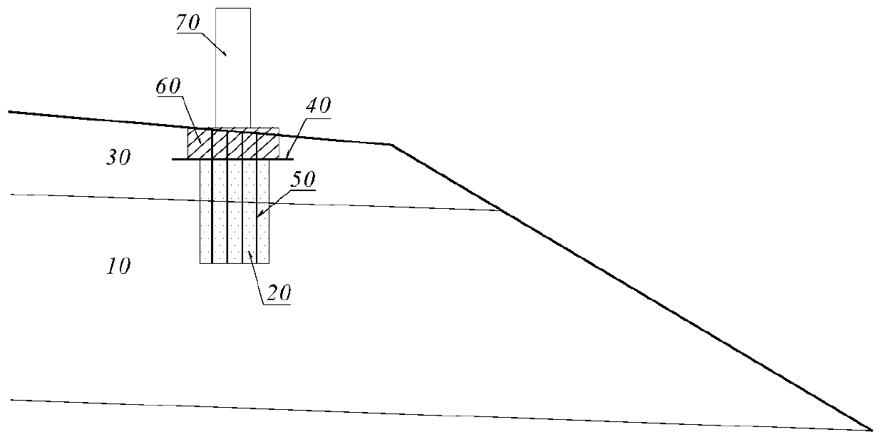
Figure 1
Abstract
Description
Technical field
[0001] The invention relates to railway engineering, in particular to a construction method of a high-speed railway catenary pillar foundation structure. Background technique
[0002] The catenary pillar foundation set on the railway subgrade is usually after the subgrade filling is completed, the foundation pit of the catenary pillar foundation is excavated by a rotary drilling machine or manual digging, and then reinforced concrete is poured into the foundation pit. This construction method has the following problems:
[0003] (1) Excavation of a 2-3m deep small-diameter foundation pit after the roadbed is filled is difficult and low in efficiency;
[0004] (2) Excavation of foundation pits affects the compactness of the filled roadbed, and has a greater impact on high-speed railways;
[0005] (3) When the filled roadbed is equipped with a waterproof and drainage geotechnical material layer, the excavation is very easy to damage the waterproof and drainage geotechni...
Examples
Embodiment Construction
[0029] The present invention will be further explained below in conjunction with the drawings and embodiments:
[0030] Reference figure 1 , The construction method of a high-speed railway catenary pillar foundation structure provided by the present invention includes the following steps:
[0031] ① Fill the lower part of the subgrade 10 in layers to the elevation position of the bottom of the catenary pillar foundation;
[0032] ②Continue to fill up the subgrade subgrade 10 and subgrade surface structure 30 above the bottom elevation of the catenary pillar foundation in layers, and fill the corresponding position of the catenary pillar foundation with water-permeable filler to form the water-permeable filler material 20 until the subgrade surface structure 30 20-30cm below the top surface;
[0033] ③Lay a layer of composite geomembrane 40 on the top of the water-permeable filling material 20, the size of the composite geomembrane 40 is larger than that of the contact net pillar foun...