
Gate device for small water conservancy project
A technology for water conservancy projects and gates, which is applied in the field of gate devices in small-scale water conservancy projects. It can solve the problems of gate plate damage, affect the closure of the gate plate, and easy oxidation of the interface, so as to improve the sealing performance, prolong the service life, and increase the oxidation resistance. performance effect
Patent Information
- Authority / Receiving Office
- CN · China
- Current Assignee / Owner
- Publication Date
- 2020-02-28
Smart Images
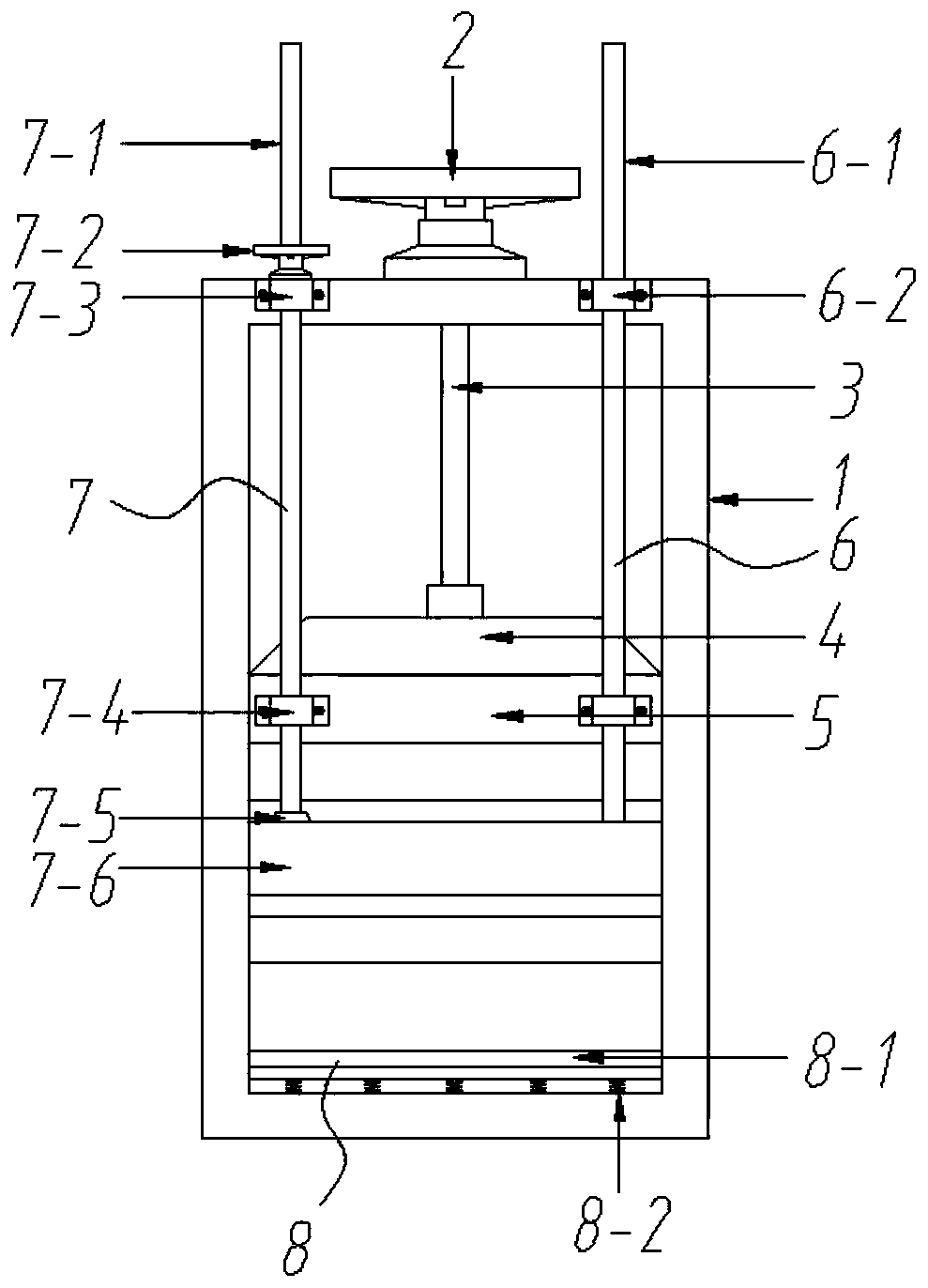
Figure 1 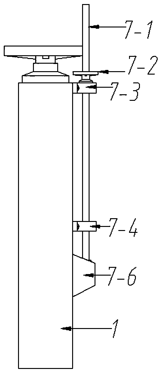
Figure 2 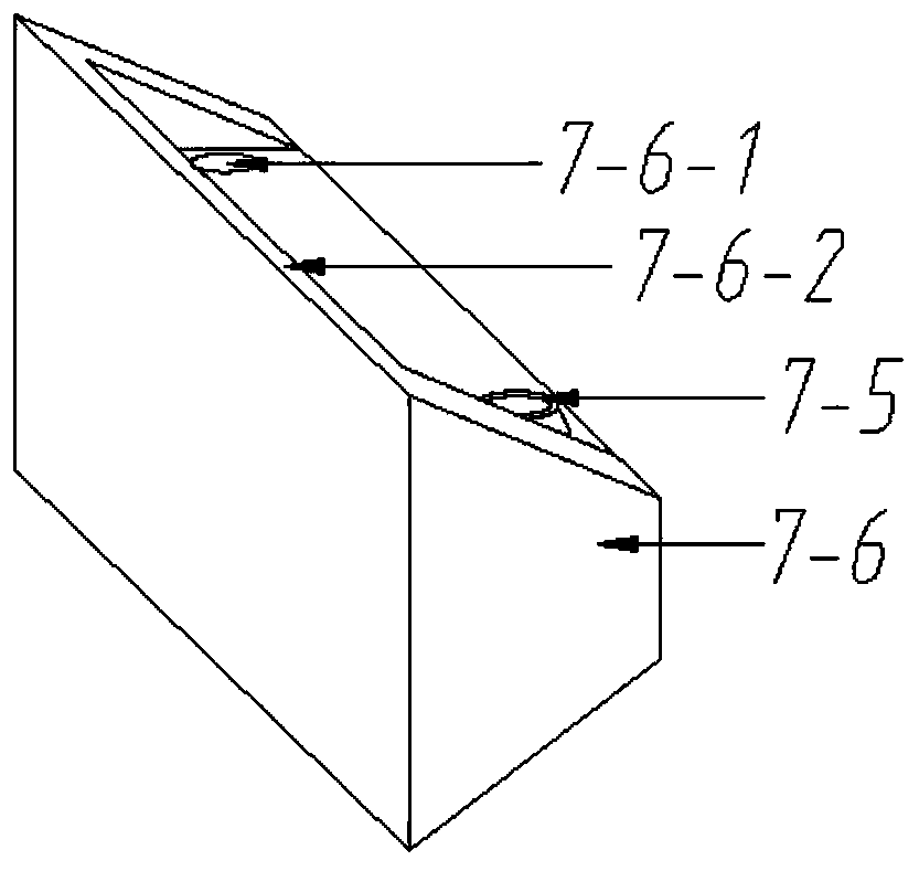
Figure 3
Abstract
Description
technical field
[0001] The invention relates to the technical field of water conservancy projects, in particular to a gate device for small water conservancy projects. Background technique
[0002] The gate is used to close and open the control facility of the discharge (discharge) channel. An important part of hydraulic structures, it can be used to intercept water flow, control water level, regulate flow, discharge sediment and floating objects, etc.
[0003] Because the gate plate has been in contact with water for a long time, the interface between the two is prone to oxidation, and the oxidized gate plate is prone to damage, which affects the normal closure and discharge of water conservancy. At the same time, after the gate is put into use for a long time, the impurities entrained in the water etc. are easy to deposit at the bottom of the gate frame, affecting the closing of the gate plate, which needs to be improved urgently. Contents of the invention
[0004] The...
Examples
specific Embodiment approach 1
[0033] Such as Figure 1-Figure 9 As shown, this specific embodiment adopts the following technical scheme: it includes a gate frame 1, a gate lifting hand wheel 2, a gate lifting screw 3, a gate 4, and a horizontal bar 5; the middle part of the gate frame 1 is fixed with a horizontal bar 5 , a flashboard 4 is inserted up and down in the horizontal bar 5, and the flashboard edge strips 4-1 on the left and right sides of the flashboard 4 are locked with the flashboard edge strip slots 1-1 on the left and right inner walls of the gate frame 1; The upper part of the gate 4 is screwed with a gate lifting screw 3, and the upper end of the gate lifting screw 3 is screwed into the gate lifting hand wheel 2, and the gate lifting hand wheel 2 is screwed on the top of the gate frame 1; It also includes a guide mechanism 6, a protection mechanism 7 and an accumulation prevention mechanism 8;
[0034] The above-mentioned guiding mechanism 6 is composed of a guide rod 6-1 and a No. 3 bear...
specific Embodiment approach 2
[0045] see Figure 10-Figure 13 , the difference between this specific embodiment and the specific embodiment one is: the protective plate lifting hand wheel 7-2 is replaced by a driven gear 7-9, and the driven gear 7-9 in the two protection mechanisms 7 is all connected with the driving gear 7-11 meshing setting, the driving gear 7-11 is socketed and fixed on the output shaft of the motor 7-10, the motor 7-10 is fixed on the top surface of the gate frame 1, the motor 7-10 is connected to the external power supply, and the rest of the structure and The connection relationship is the same as that in the first embodiment.
[0046] The motor 7-10 in this embodiment drives the driving gear 7-11, thereby driving the driven gear 7-9 to rotate, which solves the time-consuming and labor-intensive problems caused by manually pulling the protective plate to lift the handwheel.