
Oil-immersed capacitor unit structure for locomotive roof
A capacitor unit, capacitor technology, applied in the direction of capacitors, electrical components, etc., can solve the problems of high-intensity vibration, high-voltage capacitors, etc., and achieve the effect of high-intensity vibration amplitude
Patent Information
- Authority / Receiving Office
- CN · China
- Patent Type
- Applications(China)
- Current Assignee / Owner
- Publication Date
- 2020-08-04
Smart Images
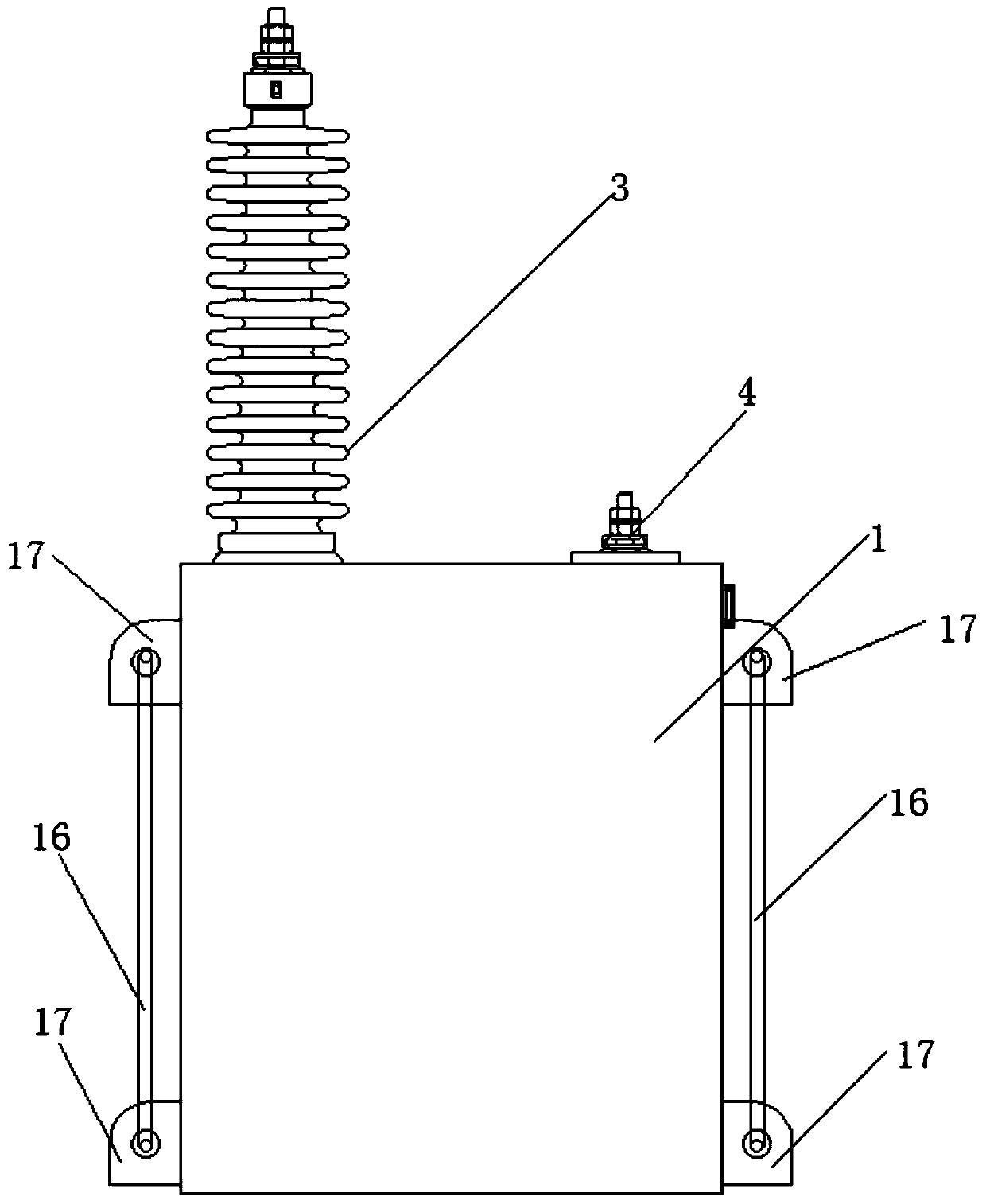
Figure 1 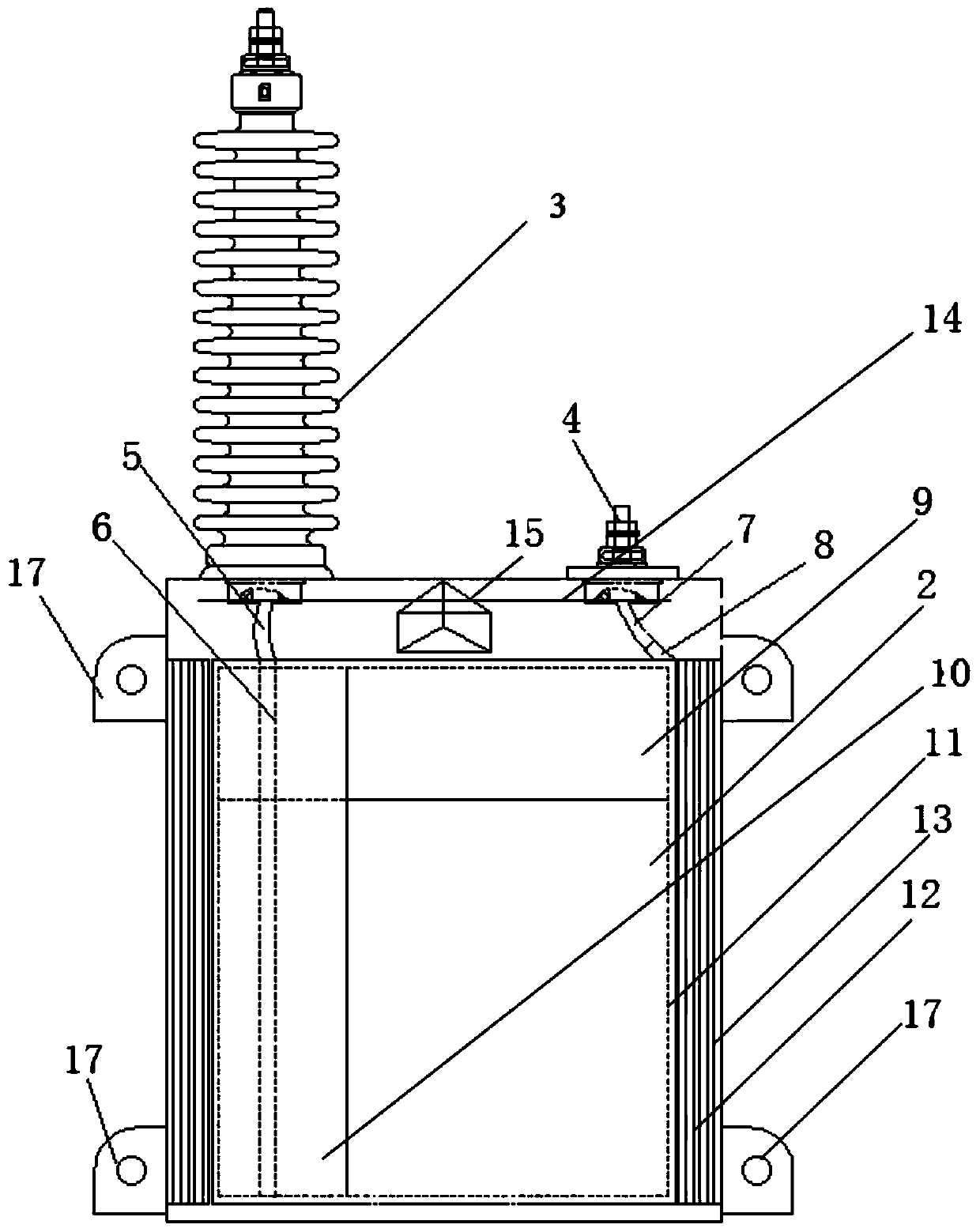
Figure 2
Abstract
Description
technical field
[0001] The invention belongs to the technical field of power capacitor units, and relates to an oil-immersed capacitor unit structure for a locomotive roof. Background technique
[0002] The capacitor is composed of several parts such as the core, the shell, and the outlet porcelain sleeve. There are hanging plates on both sides of the box wall for installation, and the grounding bolts are installed on one side of the hanging plate. The shell is formed and welded by stainless steel plates.
[0003] The rated voltage of a single capacitor commonly used in domestic substations is generally <10kV, and the withstand voltage between terminals is 2.15U N , there is no special requirement for the anti-seismic performance of a single capacitor. The unit voltage of the capacitor used on the locomotive roof is 40kV. During the operation process, the signal of a certain frequency band needs to be filtered out, and it must be able to withstand high voltage and vibrati...
Examples
Embodiment Construction
[0020] The present invention will be described in detail below in conjunction with the accompanying drawings and specific embodiments.
[0021] A kind of oil-immersed capacitor unit structure for locomotive roof of the present invention, as figure 1 , 2 As shown, it includes a capacitor case 1, and the inside of the capacitor case 1 is provided with a capacitor core 2, and the upper end of the capacitor case 1 is respectively provided with a capacitor bushing 3 and a grounding terminal 4, and the capacitor bushing 3 is connected to the Connect piece A6, connecting piece A6 is connected to the outlet end of capacitor core 2; grounding terminal 4 is connected to connecting piece B8 through bushing tail wire B7, connecting piece B8 is connected to the incoming line end of capacitor core 2, capacitor core 2 is covered with a U-shaped liner 9, and the U-shaped liner 9 covers the top surface and the front and rear sides of the capacitor core 2 respectively;
[0022] The left side ...