
Metal additive forming part surface heat transfer coefficient simulation method based on heat flow coupling
A metal additive, heat transfer coefficient technology, applied in complex mathematical operations, electrical digital data processing, CAD numerical modeling, etc., can solve problems such as errors, achieve accurate numerical simulation results and save costs
Patent Information
- Authority / Receiving Office
- CN · China
- Current Assignee / Owner
- Publication Date
- 2021-04-23
Smart Images
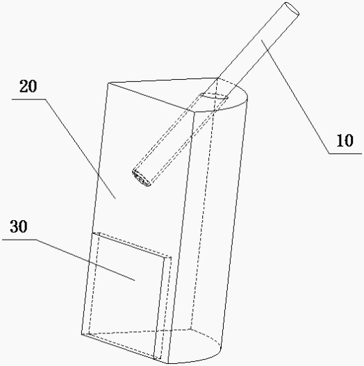
Figure 1 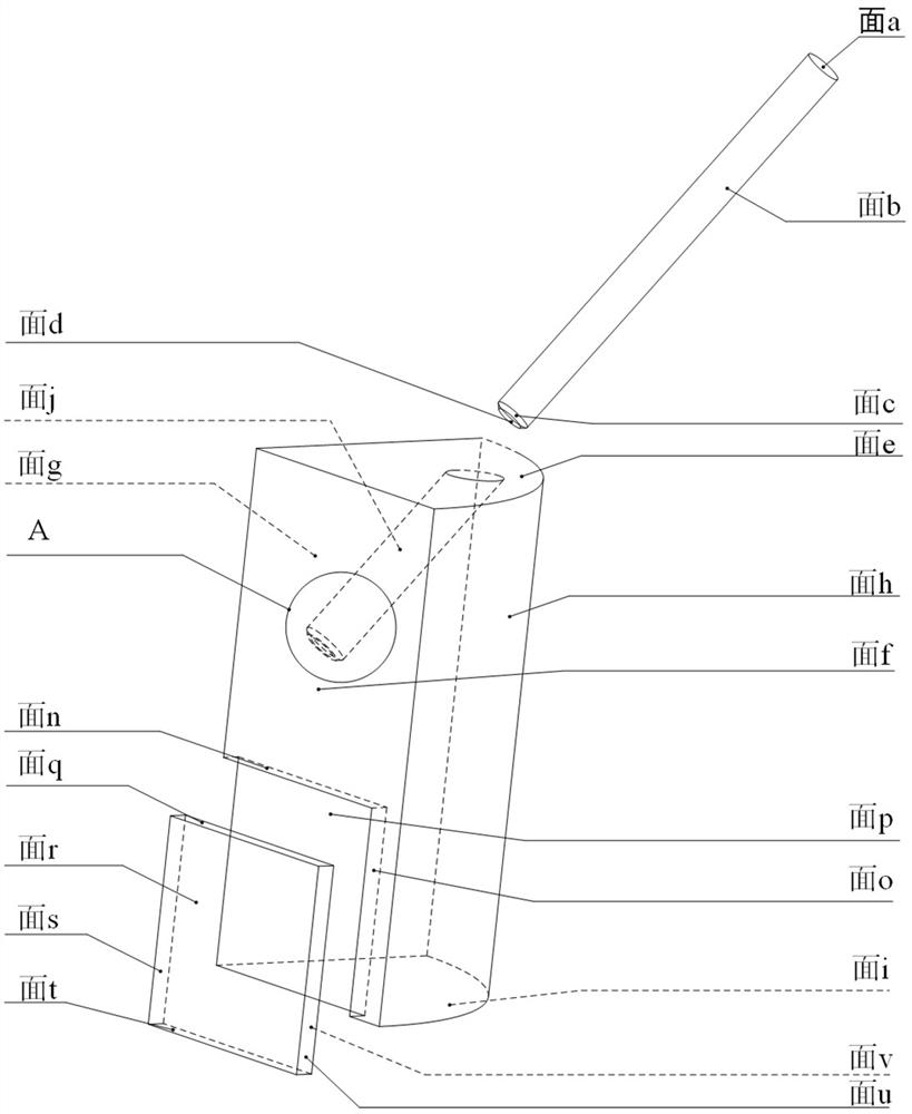
Figure 2 
Figure 3
Abstract
Description
technical field
[0001] The invention relates to the technical field of metal additive printing, in particular to a method for simulating the surface heat transfer coefficient of a metal additive formed part based on heat flow coupling. Background technique
[0002] Metal laser additive manufacturing technology is an emerging processing and manufacturing technology. Compared with traditional subtractive technology, it has the following characteristics: (1) It can process and manufacture complex inner cavity structures; (2) It can process slender and thin-walled structures ; (3) Damaged parts can be repaired. In actual production and manufacturing, due to the variability of the processing environment, the printed parts have defects such as voids, cracks, and poor melting. Therefore, it is necessary to explore the factors that affect the quality of the processed parts from the perspective of computer simulation.
[0003] When simulating metal additive manufacturing, accurate t...
Examples
Embodiment Construction
[0037] A method for simulating the surface heat transfer coefficient of a metal additive formed part based on heat flow coupling provided in this embodiment includes the following steps:
[0038] (1) Use 3D drawing software to compile the geometric model of the printed part and the flow field around the printed part, and perform finite element analysis on the geometric model, which includes the geometric model of the flow field inside the nozzle 10, the geometric model of the flow field outside the nozzle Model 20 and printed part geometric model 30; present embodiment adopts SolidWorks software to draw respectively the flow field geometric model 10 in the nozzle, the flow field geometric model 20 outside the nozzle and the printed part geometric model 30, and the geometric model drawn is assembled, Such as figure 1 As shown, the geometric model 10 of the flow field inside the nozzle, the geometric model 20 of the flow field outside the nozzle and the geometric model 30 of th...