
Quality rapid detection device for apple sugar detection
A detection device, apple candy technology, applied in the direction of measuring devices, sampling devices, analysis materials, etc., can solve the problems of unfavorable procurement and processing portable applications, inability to obtain the internal quality of fruits, weak signals, etc., to achieve fully comprehensive and intuitive detection results , accurate and efficient detection, and easy operation
Patent Information
- Authority / Receiving Office
- CN · China
- Patent Type
- Applications(China)
- Current Assignee / Owner
- Publication Date
- 2022-03-01
Smart Images
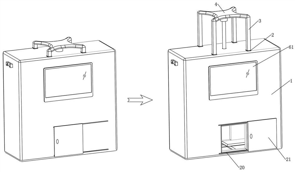
Figure 1 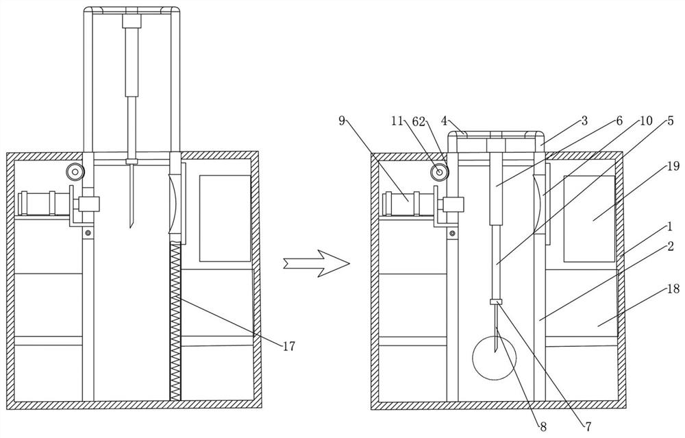
Figure 2 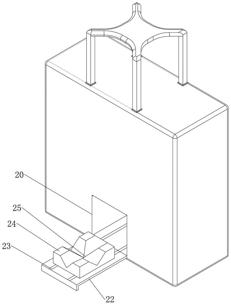
Figure 3
Abstract
Description
technical field
[0001] The invention belongs to the technical field of fruit sugar detection equipment, and in particular relates to a rapid detection device mainly used for detection of sugar content in apples. Background technique
[0002] At present, the general apple grading method is generally manual. Operators grade apples according to the size, shape and defects of the apples. The productivity is low and the grading effect is unstable. Although the approximate quality of many apples can be judged by naked eyes, artificial random selection will be affected by human factors, resulting in the problem that the representativeness of the samples is not strong. With the improvement of people's quality of life, consumers not only pay attention to external qualities such as size, color and appearance, but also internal qualities such as taste, sugar content, acidity and vitamin content when purchasing fruits. On the other hand, with the strict export inspection and the gradua...
Examples
Embodiment 1
[0044] Example 1: A device for the detection of fruit sugar, especially for the rapid detection of apple quality. Regarding the existing detection of apple sugar, it is necessary to transfer the sample to the sample pool of the Raman spectrometer for laboratory analysis, resulting in low efficiency and use. Inconvenient problem, this embodiment provides such as figure 1 As shown in the device, the device mainly includes a closed rectangular box 1, portable components such as handles or straps can be installed on both sides, and display components can be installed on the side walls, as well as other auxiliary accessories.
[0045] From figure 1 It can be seen from the figure that there is a left and right through channel at the center of the lower part of the box body 1, and this channel is used as a sample delivery channel for placing corresponding fruits. The sample feeding channel is provided with a door part, which is closed in the non-use state. A door component such as ...
Embodiment 2
[0055]Embodiment 2: On the basis of Embodiment 1, lower flap doors 22 are respectively hinged at the bottom of the channel openings 20 on both sides below the box body, so that the lower flap doors 22 on both sides can be expanded to both sides after being opened to expand the channel width. By arranging a spacer on the outside of the lower flap door 22, it can be kept flush with the internal sampling channel after being deployed. From image 3 It can be seen that parallel rails 23 are provided on the inner surfaces of the down-turning doors 22 on both sides and at the bottom of the sample feeding channel respectively. When the down-turning doors 22 on both sides are respectively expanded outwards, each channel is sequentially connected end to end. A slider 24 is installed on the track 23, and the upper part of the slider 24 is distributed with V-shaped grooves along the horizontal and vertical directions to form a cross card slot 25, which is used to carry and restrain the fr...
Embodiment 3
[0057] Embodiment 3: another kind of rapid detection device, such as Figure 4 As shown, the main structure is the same as that of Embodiment 1, the difference is that the electric push rod 26 is directly connected to the upper part of the push rod 5 in this embodiment, and the upper part of the electric push rod 26 is fixed on the top of the box. At the same time, limit switches or position sensors are arranged at the upper and lower movement limit positions of the electric push rod to constrain its upper and lower limit positions, so that it is in the sampling area when it is at the lower limit position, and it is in the detection area when it is at the upper limit position. Control the start and stop of the electric push rod through the switch, or control the start and stop of the electric push rod through the controller and buttons.