
Roller device for papermaking equipment and papermaking equipment
A papermaking equipment and roller technology, which is applied in the field of the connection structure between the roller and the motor for papermaking equipment, can solve the problems of large space occupied by the production line, power loss, low transmission efficiency, etc.
Patent Information
- Authority / Receiving Office
- CN · China
- Patent Type
- Applications(China)
- Current Assignee / Owner
- Publication Date
- 2022-07-01
Smart Images
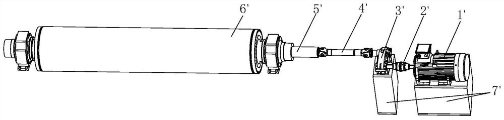
Figure 1 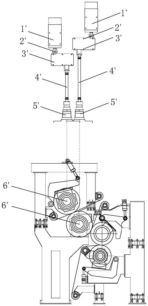
Figure 2 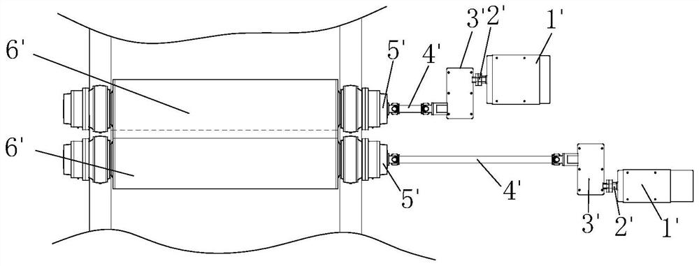
Figure 3
Abstract
Description
technical field
[0001] The invention relates to a connection structure of a roller for papermaking equipment and a motor, in particular to a roller device for papermaking equipment and papermaking equipment. Background technique
[0002] The existing installation structure of rollers and motors for papermaking equipment is as follows: figure 1 As shown, it includes a motor 1' fixedly installed on the mounting table 7', a reduction box 3', a coupling 2' connecting the motor 1' and the reduction box 3', an input shaft 5' and a connection with the input shaft 5' the roller 6'. See figure 2 , because the rollers 6' are arranged on the upper and lower layers of the production line equipment, if the motor 1' is installed on the upper and lower layers of the same installation platform 7', due to the volume limitation of the motor 1' or the reduction box 3', the upper and lower layers There is interference between the motor 1' and the reduction box 3', and the length of the roll...
Examples
Embodiment 1
[0076] See Figures 4 to 8 , the second rotating shaft 300 includes a transmission section 310 supported by the second bearing seat 220 and a mounting section 320 extending into the axial through hole 111 of the motor rotating shaft 100 . The interference connection structure of this embodiment includes: an installation section 320 extending into the axial through hole 111 of the motor shaft 100 ; a connection formed between the axial through hole 111 of the motor shaft 100 and the installation section 320 The annular gap of the space 10; the outer cone ring 600 and the inner cone ring 500 are installed in the connecting space 10, the outer cone ring 600 is sleeved on the installation section 320, and the inner cone ring 500 is sleeved on the outer cone ring 600; The baffle plate 700 at the end of the installation section 320 is detachably screwed, and the baffle plate 700 is used to axially limit the inner cone ring 500 and / or the outer cone ring 600 and provide an axial pres...
Embodiment 2
[0092] The difference between this embodiment and the first embodiment is that the axial through hole and the second rotating shaft of the roller form a conical surface interference connection structure. For specific examples, see Figure 20 and Figure 21 , the axial end face of the mounting section 310' is provided with a threaded hole 311'. The axial through-hole 110' of the motor 100' includes a through-hole mounting section 112' with a constant diameter and a through-hole connecting section 113' with a gradually reduced diameter along the axial direction of the through-hole mounting section (112'). A step 70 is formed at the intersection of the segment 112 ′ and the through-hole connecting segment 113 ′, and a baffle plate 700 is provided on the end face of the step 70 . The second rotating shaft 300' of the roller is provided with a truncated mounting section 310'. For specific connections, see Figure 21 , the mounting section 310' of the second rotating shaft of th...
Embodiment 3
[0094] See Figure 22 , the difference between this embodiment and the first embodiment is: the elastic connection structure between the elastic member 400 ′ and the motor 100 . The motor support 230 in this solution can be fixed on the bearing seat 220' or fixed on the equipment. The elastic member 400' is a rubber elastic member or a spring, etc. The motor casing 140 is provided with a motor axial through hole (not shown), the elastic member 400' is provided with an elastic member through hole (not shown), and the screws 30 pass through the motor in sequence After the bracket 230 , the through hole of the elastic member and the axial through hole of the motor, the elastic member 400 ′ is arranged between the motor bracket 230 and the motor 100 . The design provides flexible support for the motor, so that the motor can adapt to the micro-movement changes of the rotation or deformation of the roller, and avoid damage to the motor due to non-uniform over-restraint.