
Mechanical manipulator for surgical instruments
a mechanical manipulator and surgical instrument technology, applied in mechanical apparatus, surgical forceps, gearing, etc., can solve the problems of high acquisition and maintenance costs, non-ergonomic, non-intuitive and missing in adequate stiffness, precision and force feedback, and difficulty in learning and performing such procedures with current laparoscopic equipment. , to achieve the effect of high payload capacity, high payload capacity, and high dexterity
Patent Information
- Authority / Receiving Office
- US · United States
- Patent Type
- Patents(United States)
- Current Assignee / Owner
- Publication Date
- 2018-10-09
Smart Images
Figure 1 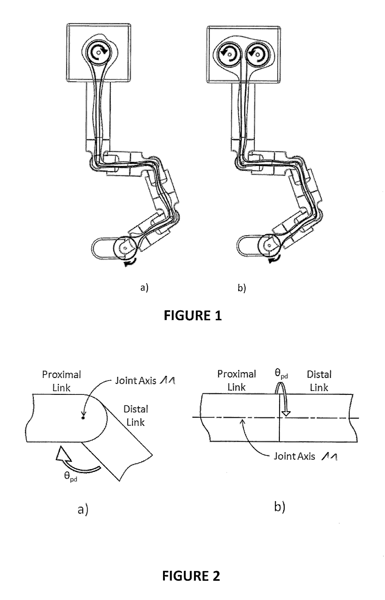
Figure 2 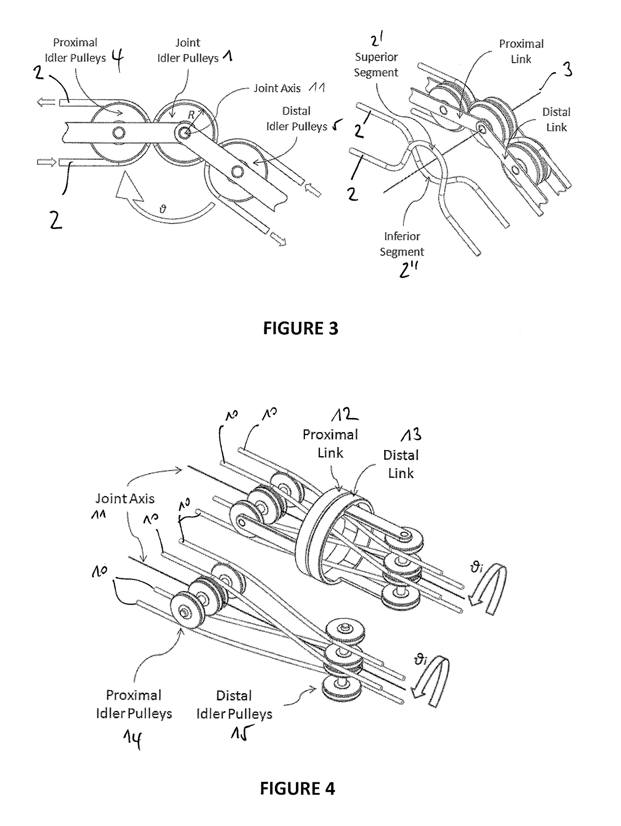
Figure 3
Abstract
Description
CROSS-REFERENCE TO RELATED APPLICATIONS
[0001] This application claims the benefit of European patent application No 10187088.9 and No 10187097.0, both filed on Oct. 11, 2010, the entire disclosure of which is hereby incorporated herein by reference.FIELD OF THE INVENTION
[0002] The present invention relates to the field of remotely actuated mechanisms and devices for use in surgical procedures within the abdominal cavity, using reduced incisions in the abdominal wall.BACKGROUND OF THE INVENTION
[0003] A major progress in abdominal surgery has occurred during the last decades with the introduction of laparoscopic and minimally invasive techniques. These innovative procedures focused much attention due to their several advantages: smaller abdominal incisions needed, resulting in faster recovery of the patient, improved cosmetics, and shorter stay in the hospital. The safety, efficiency and cost-effectiveness of laparoscopic surgery have subsequently been demonstrated in clinical trials for...
Examples
Embodiment Construction
[0102]The present invention will be better understood from the following detailed description and with reference to the drawings which show:
[0103]FIG. 1 illustrates two different architectures for remote actuated cable driven systems, a) One actuated pulley per DOF b) Two actuated pulleys per DOF;
[0104]FIG. 2 illustrates (a) a Pivot Joint and (b) a Co-axial Joint;
[0105]FIG. 3 illustrates a cable rooting along a Pivot Joint, (a) being a 2D view and (b) being a perspective 3D view;
[0106]FIG. 4 illustrates the problem of the cable routing along a co-axial joint;
[0107]FIG. 5 further illustrates the problem of the cable routing along a co-axial joint;
[0108]FIG. 6 illustrates a Co-axial joint Concept Development;
[0109]FIG. 7 illustrates a Co-axial joint Concept, for a 2-DOF example;
[0110]FIG. 8 illustrates a bead chain turning the idler cylinder;
[0111]FIG. 9 illustrates a use of two ball bearings to mount an idler tube;
[0112]FIG. 10 illustrates a Radial and axial restriction of the joint ...