
Pneumatic tire
a technology of pneumatic tires and treads, which is applied in the direction of tyre tread bands/patterns, vehicle components, transportation and packaging, etc., to achieve the effects of reducing rigidity of tread portions, high independence, and dry performan
Patent Information
- Authority / Receiving Office
- US · United States
- Patent Type
- Patents(United States)
- Current Assignee / Owner
- Publication Date
- 2019-10-29
Smart Images
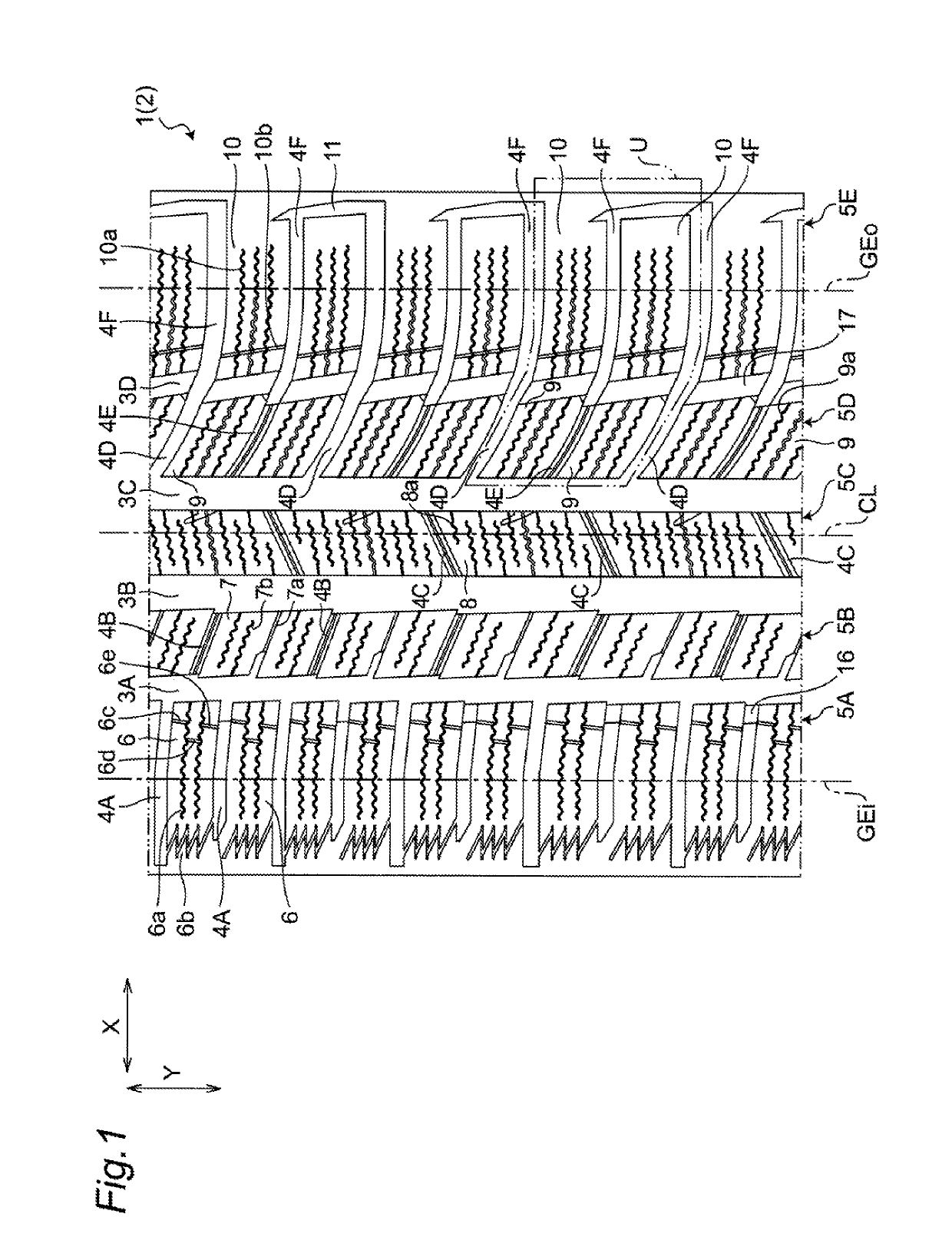
Figure 1 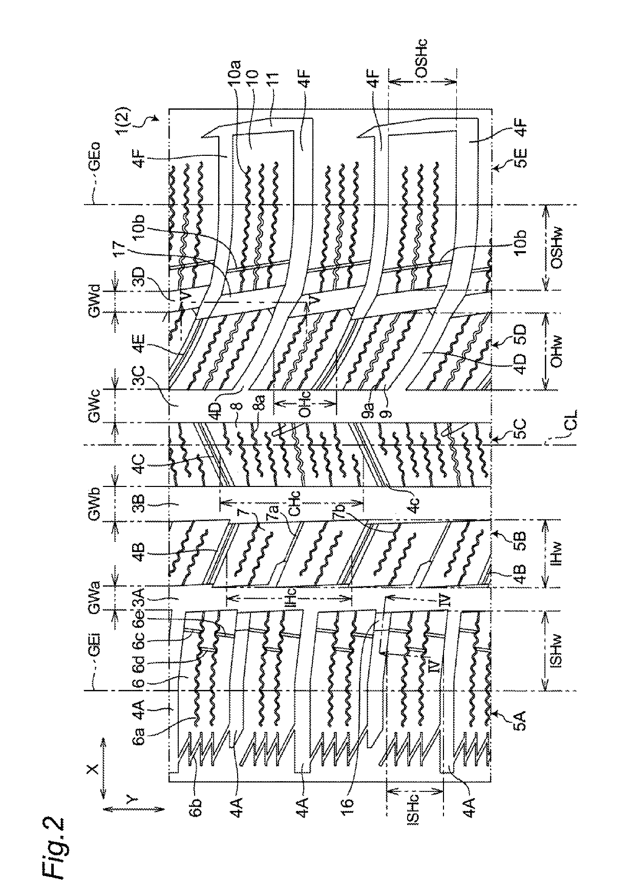
Figure 2 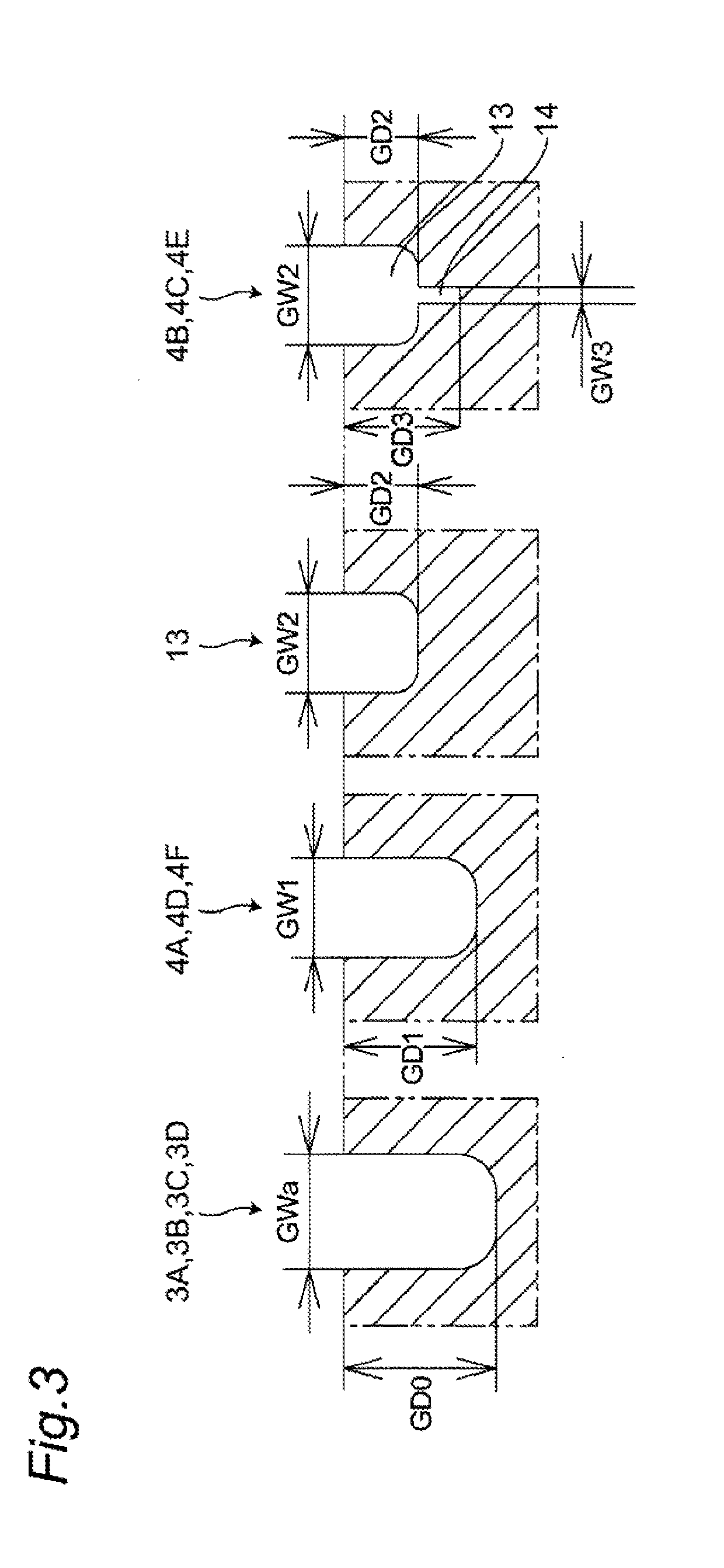
Figure 3
Abstract
Description
CROSS-REFERENCE TO RELATED APPLICATIONS
[0001] This application claims priority of Japanese Patent Application Nos.: 2015-198703, 2015-198704, and 2015-198707 filed on Oct. 6, 2015, the contents of which are incorporated herein by reference.BACKGROUND OF THE INVENTION
[0002] Technical Field
[0003] The present invention relates to a pneumatic tire.
[0004] Related Art
[0005] WO 2012 / 111589, Japanese Patent 5639461, Japanese Patent 3376342 and JP 2012-96782 A disclose a pneumatic tire having a plurality of block rows extending in a tire circumferential direction. Each block row has a plurality of blocks arranged in a row in the tire circumferential direction. However, it is not always the case with these conventional pneumatic tires that the pneumatic tire has succeeded in enhancing all of the following: drive performance, braking performance and turning performance while ensuring drain performance.
[0006] There have been proposed tires having various tread patterns for the purpose of enhancing mo...
Examples
second embodiment
[0105]Referring to FIG. 6, on a tread portion 2 of a tire 1 according to a second embodiment, none of inner longitudinal slits 6c, 6d, 6e on an inner shoulder block 6, first raised portions 16, and second raised portions 17 (see also FIG. 1 and FIG. 2 with respect to these constitutional elements) are formed. The same goes for third to seventh embodiments described later with respect to this point.
[0106]On an outer intermediate row 5D disposed between a second center main groove 3C and an outer main groove 3D, a lateral groove 4D which is “deep groove” and a lateral groove 4E which is “shallow groove with sipes” are alternately formed. In the first embodiment, each outer intermediate block 9 which forms the outer intermediate row 5D is defined as a block defined by the second center main groove 3C, the outer main groove 3D, the lateral groove (deep groove) 4D, and the lateral groove (shallow groove with sipes) 4E. However, the lateral groove 4E which is “shallow groove with sipes” h...
third embodiment
[0127]Referring to FIG. 8, a tread portion 2 of a tire 1 according to a third embodiment differs from the tread portion 2 of the tire 1 according to the second embodiment only with respect to the configuration of the inner intermediate row 5B and the center row 5C.
[0128]On the inner intermediate row 5B, a lateral groove 40 which is “deep groove” and a lateral groove 4B which is “shallow groove with sipes” are alternately formed. Accordingly, the inner intermediate row 5B is formed of a plurality of composite blocks 22 each of which is divided by the lateral grooves 4G which are “deep grooves” (see also FIG. 9A).
[0129]In the same manner, on the center row 5C, a lateral groove 4H which is “deep groove” and a lateral groove 4C which is “shallow groove with sipes” are alternately formed. Accordingly, the center row 5C is formed of a plurality of composite blocks 23 each of which is divided by the lateral grooves 4H which are “deep grooves” (see also FIG. 9B).
fourth embodiment
[0130]Referring to FIG. 10, on a tread portion 2 of a tire 1 according to a fourth embodiment, an inner intermediate row 5B, a center row 5C, and an outer intermediate row 5D are formed of only “composite blocks” respectively.
[0131]On the inner intermediate row 5B, two lateral grooves 4B which are “shallow grooves with sipes” are formed between two lateral grooves 4G which are “deep grooves”. One composite block 24 is defined by an inner main groove 3A, a first center main groove 3B, and two lateral grooves 4G which are “deep grooves” (see also FIG. 11A).
[0132]In the same manner, on the center row 5C, two lateral grooves 4C which are “shallow groove with sipes” are formed between two lateral grooves 4H which are “deep grooves”. One composite block 25 is defined by a first center main groove 3B, a second center main groove 3C, and two lateral grooves 4H which are “deep grooves” (see also FIG. 11B).
[0133]On the outer intermediate row 5D, two lateral grooves 4E which are “shallow groov...