
Fuel injection system for a turbine engine
Patent Information
- Authority / Receiving Office
- US · United States
- Current Assignee / Owner
- Publication Date
- 2005-02-17
Smart Images
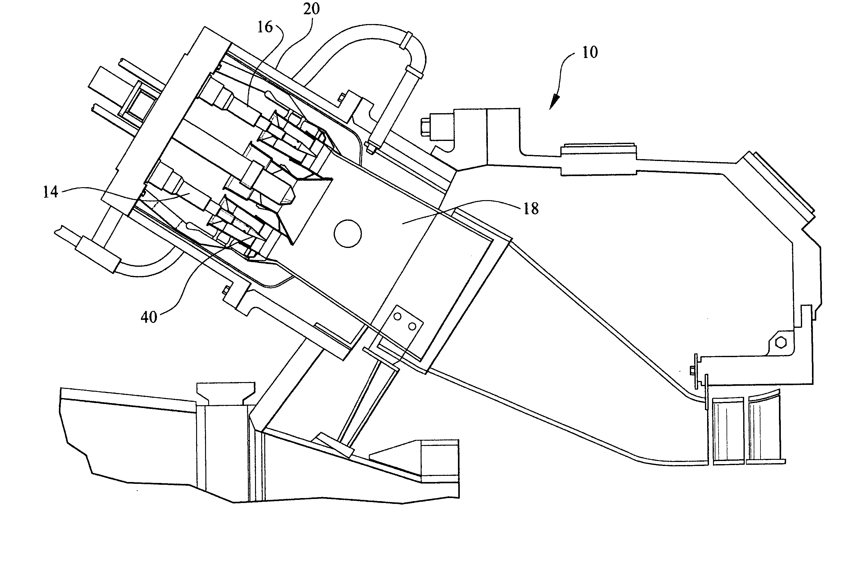
Figure 1 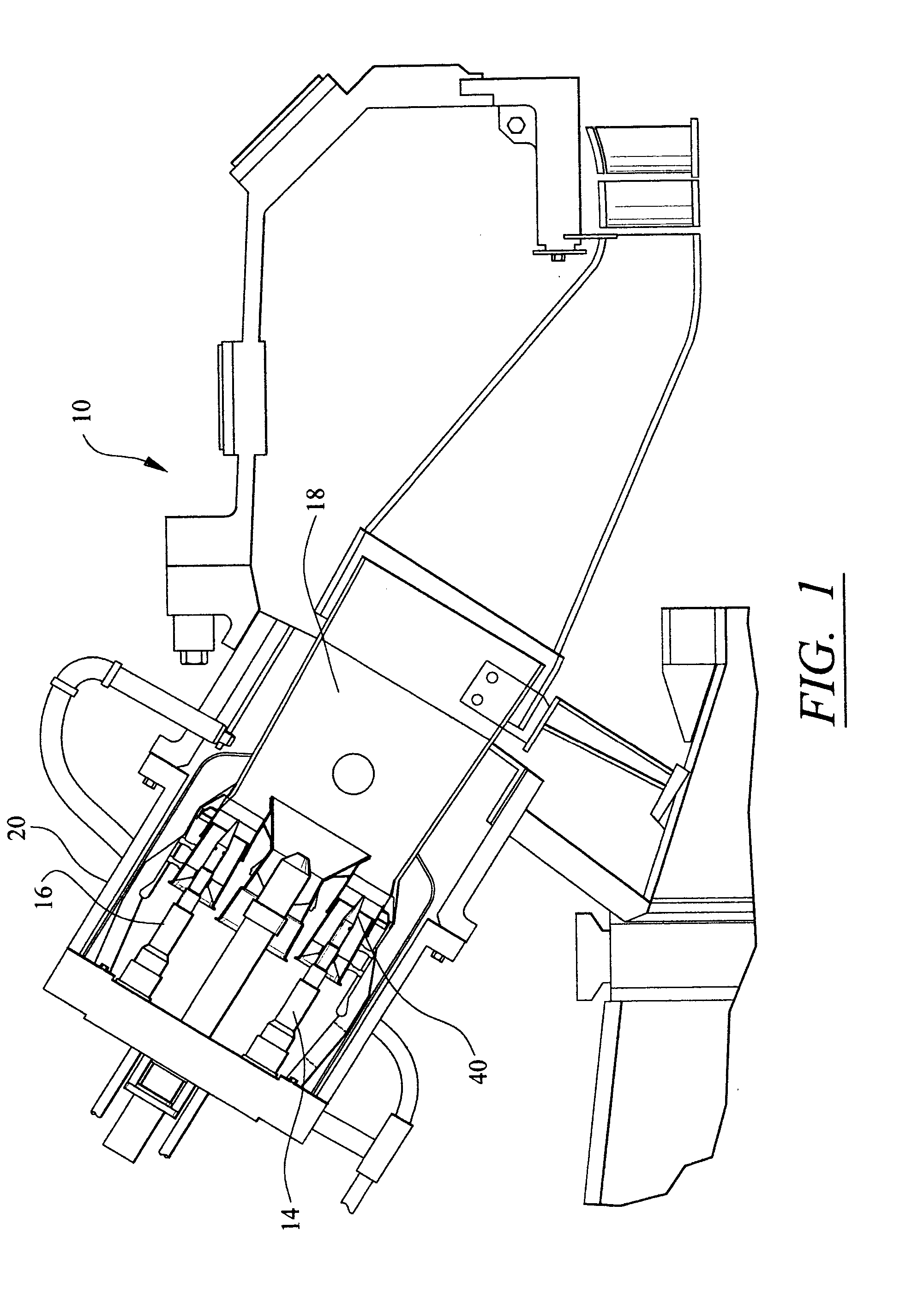
Figure 2 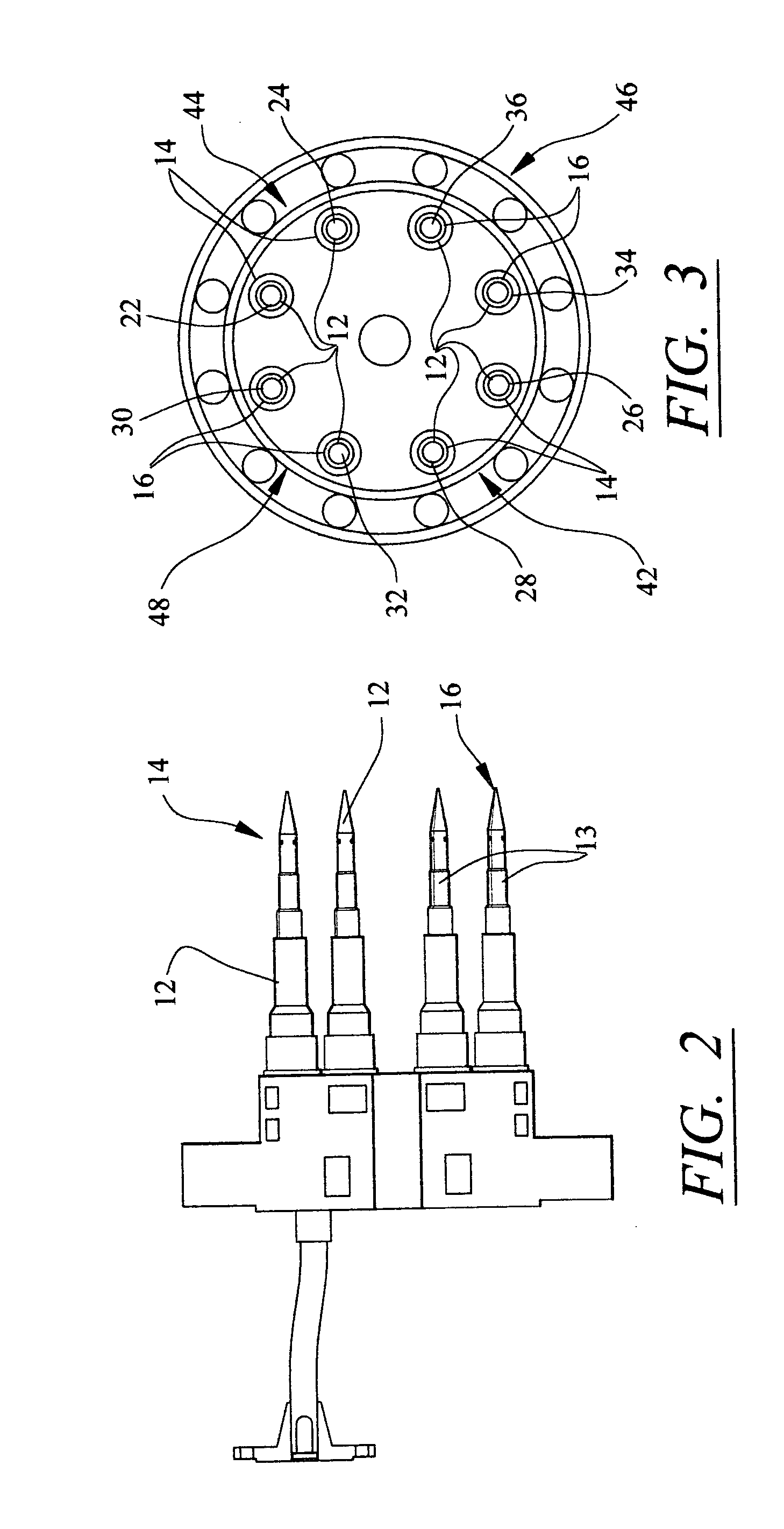
Figure 3
Abstract
Description
FIELD OF THE INVENTION
[0001] This invention is directed generally to turbine engines, and more particularly to fuel system for turbine engines. BACKGROUND
[0002] Typically, gas turbine engines include a plurality of injectors for injecting fuel into a combustor to mix with air upstream of a flame zone. The fuel injectors of conventional turbine engines may be arranged in one of at least three different schemes. Fuel injectors may be positioned in a lean premix flame system in which fuel is injected in the air stream far enough upstream of the location at which the fuel / air mixture is ignited that the air and fuel are completely mixed upon burning in the flame zone. Fuel injectors may also be configured in a diffusion flame system such that fuel and air are mixed and burned simultaneously. In yet another configuration, often referred to as a partially premixed system, fuel injectors may inject fuel upstream of the flame zone a sufficient distance that some of the air is mixed with t...
Examples
Embodiment Construction
[0017] As shown in FIGS. 1-3, this invention is directed to a fuel system 10 for a turbine engine. In particular, the fuel system 10 is directed to a dry low NOx(DLN) fuel system 10 operable as a partially premixed combustor system. The fuel system 10 is configured to allow an associated turbine engine 20 to operate at partial load conditions while producing reduced levels of CO emissions. In at least one embodiment, the fuel system 10 includes a plurality of injectors 12, as shown in FIGS. 2 and 3, for injecting fuel into a combustor 18 of a turbine engine 20, wherein the fuel system may inject fuel from less than all of the injectors 12 while the turbine engine 20 is operating at partial loads. The fuel system 10 is configured to reduce the size of the interface between the flows of the fueled injectors and unfueled injectors and thereby reduce CO emissions from the turbine engine 20.
[0018] In at least one embodiment, as shown in FIGS. 2 and 3, the fuel system 10 may be composed ...