
Optical fiber coupling having liquid crystal adaptive coupler
Patent Information
- Authority / Receiving Office
- US · United States
- Current Assignee / Owner
- Publication Date
- 2005-02-24
- Estimated Expiration
- Not applicable · inactive patent
Smart Images
Figure 1 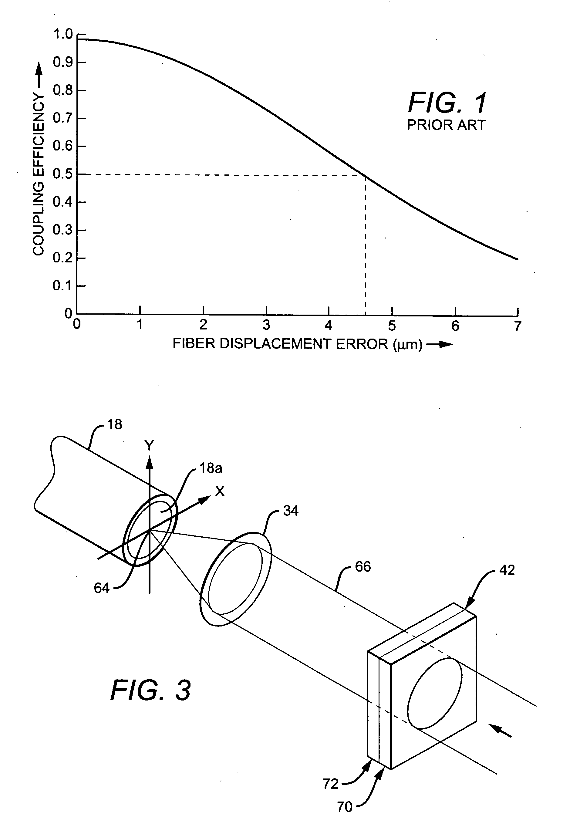
Figure 2 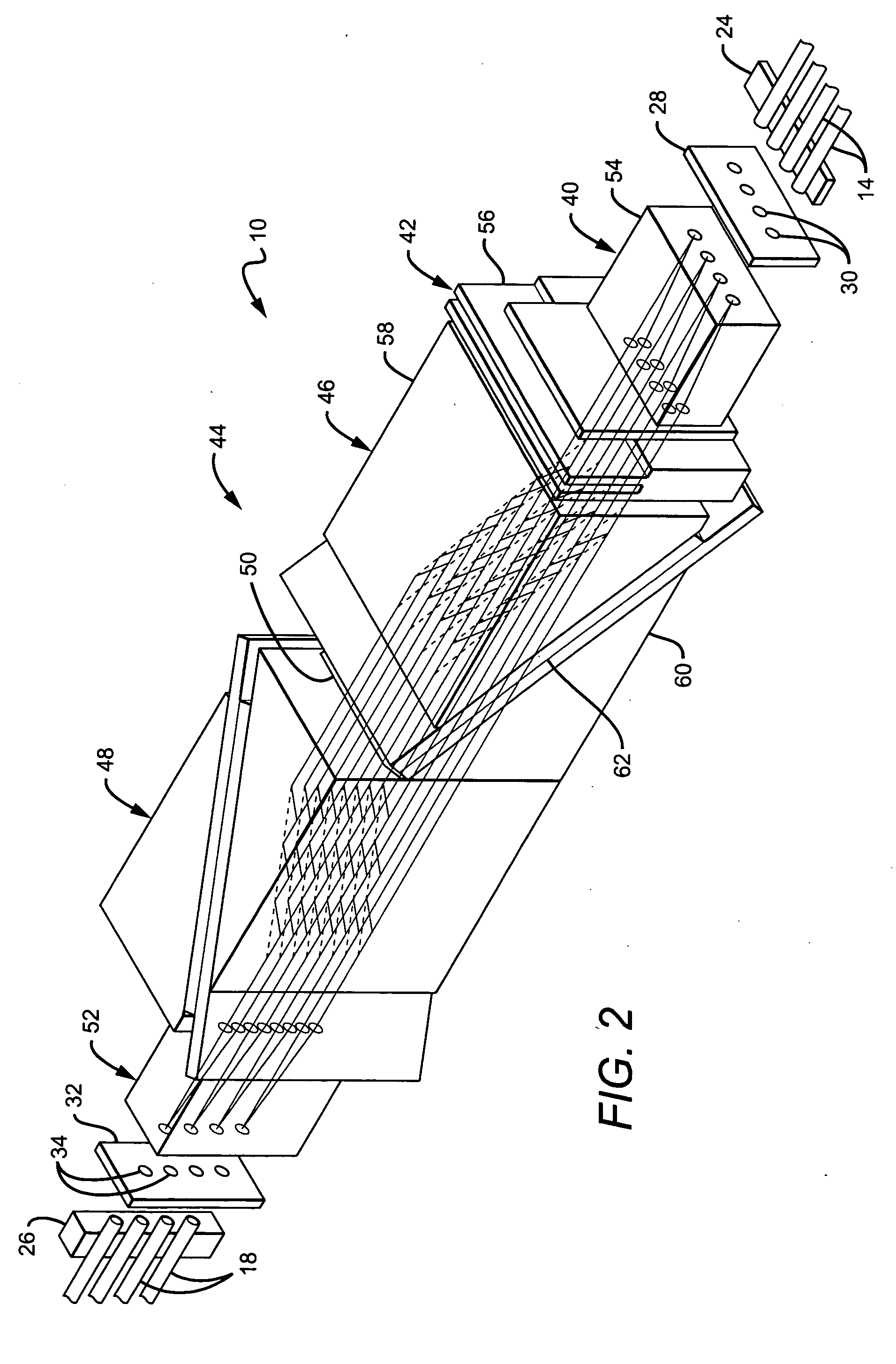
Figure 3
Abstract
Description
BACKGROUND OF THE INVENTION
[0001] 1. Field of the Invention
[0002] The present invention relates generally to optical beam steering and particularly to an optical system utilizing the electro-optical properties of liquid crystals to steer a light beam relative to a light-receiving end of an optical waveguide such as an optical fiber.
[0003] 2. Description of the Related Art
[0004] N×N optical cross connect switches used, for example, in telecommunications systems, optically couple any one of N input optical fibers to any one of N output optical fibers. Such switches comprise examples of systems that make use of various techniques for deflecting or steering a light beam emitted from a light source, in this case the light-emitting end of a selected one of the N input fibers, to the light-receiving end of an optical waveguide, here in the form of a selected one (and in some cases, more than one) of the N output fibers.
[0005] One conventional optical beam steering technique applies di...
Examples
Embodiment Construction
[0036] It will be evident to those skilled in the art that the present invention has broad utility, being applicable, by way of example and not limitation, to cross bar switches; filter arrays; attenuator arrays; antenna arrays; laser systems utilizing, for example, laser diode sources for communications or other purposes; and so forth, employing optical channels or waveguides which may take the form of optical fibers.
[0037] With reference to FIG. 2, there is shown a specific example of how the present invention may be applied. The example of FIG. 2 comprises a form of an N×N liquid crystal optical cross connect switch 10 for use, for example, in a data communications or telecommunications system.
[0038] In the specific, exemplary N×N optical switch shown in FIG. 2, N=4 so that the switch 10 can couple any selected one of four longitudinally oriented input fibers 14 with any selected one of four longitudinally oriented output fibers 18.
[0039] A support 24 secures the light-emittin...