
Method and system for improving amplifier efficiency
Patent Information
- Authority / Receiving Office
- US · United States
- Current Assignee / Owner
- Publication Date
- 2005-03-31
- Estimated Expiration
- Not applicable · inactive patent
Smart Images
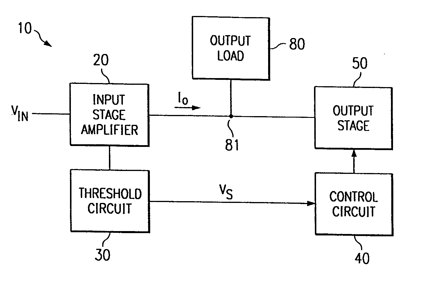
Figure 1 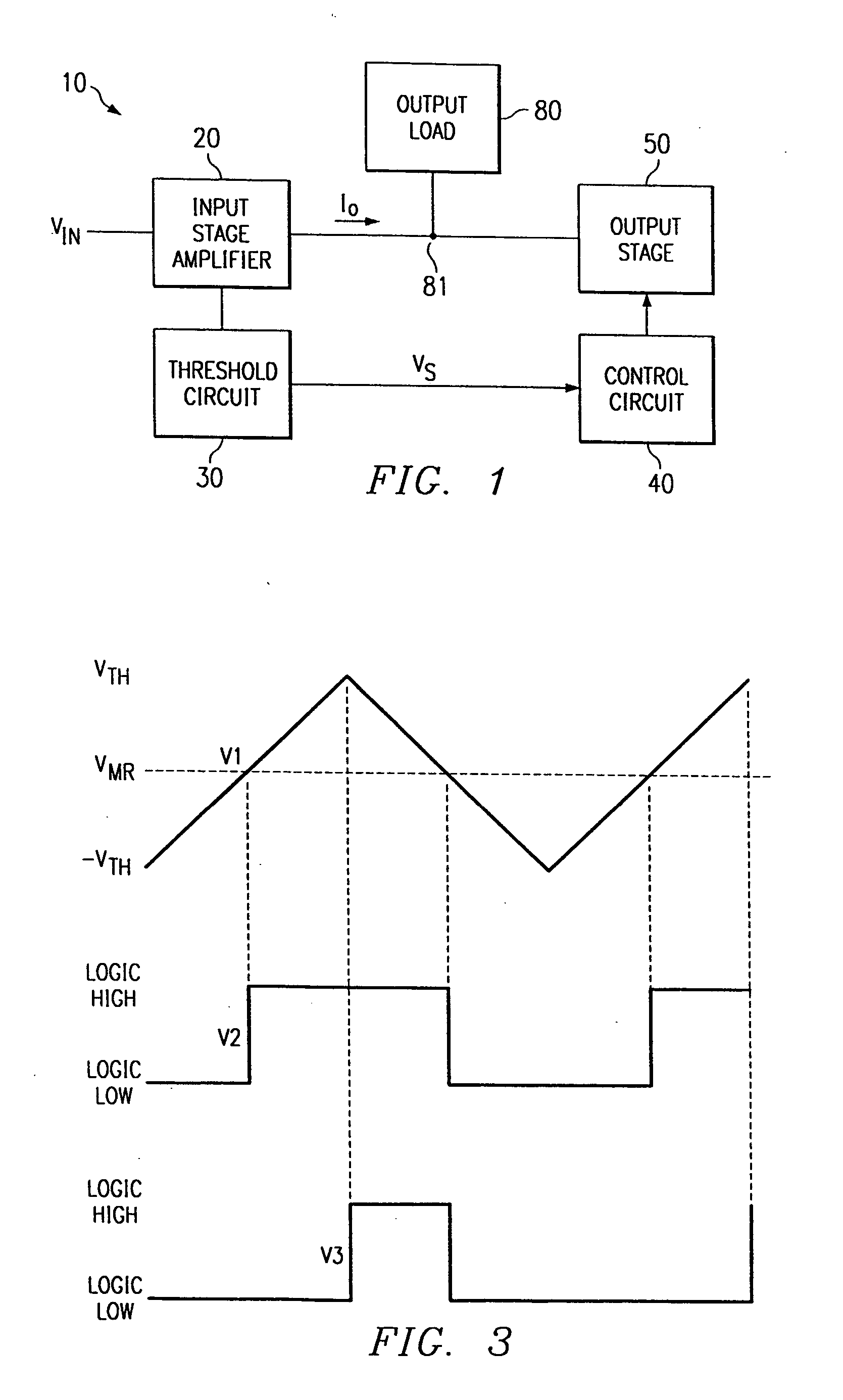
Figure 2 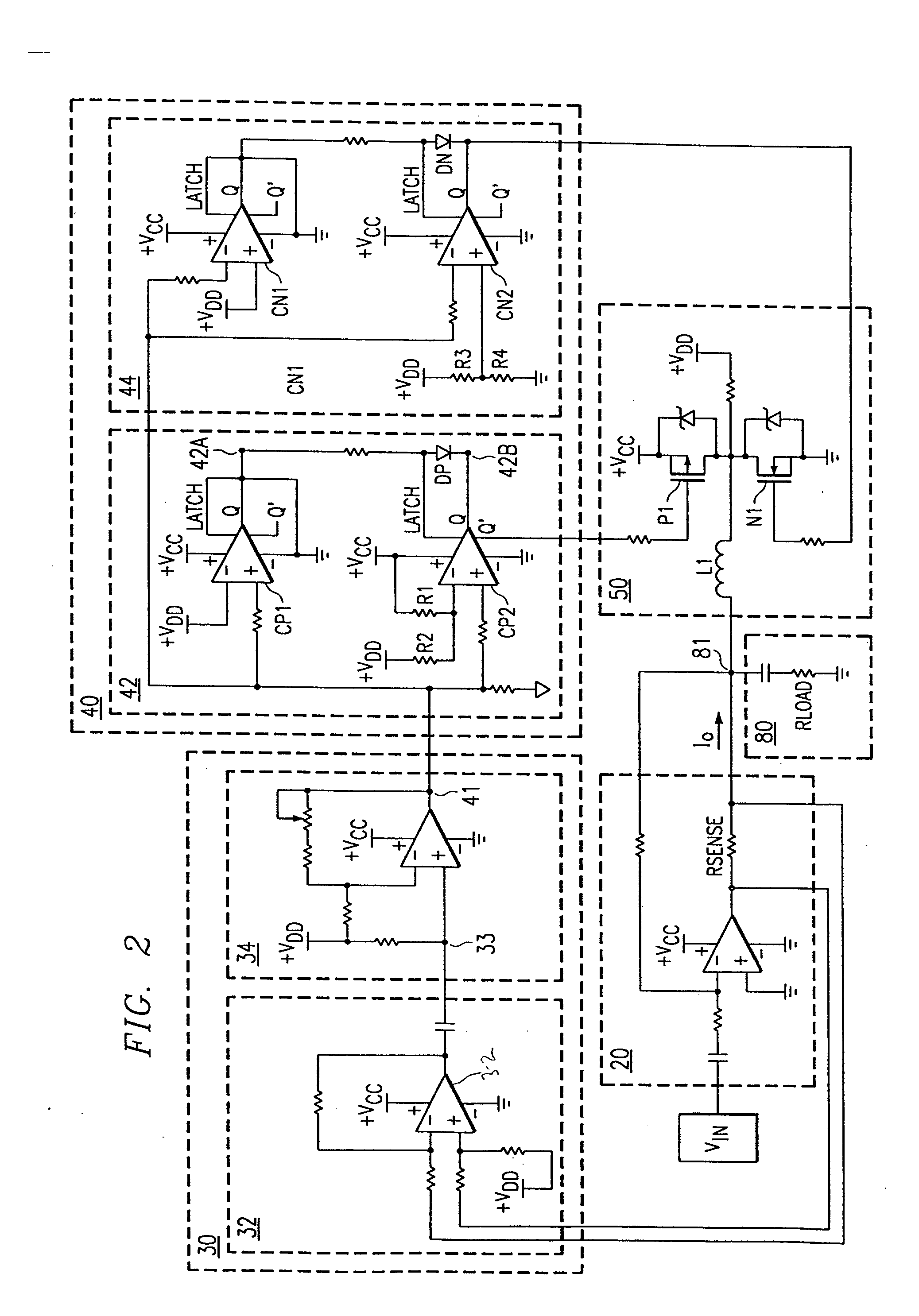
Figure 3
Abstract
Description
TECHNICAL FIELD OF THE INVENTION This invention relates generally to the field of amplifier circuits and more particularly to a method and system for improving amplifier efficiency. BACKGROUND OF THE INVENTION Amplifiers are used to increase or decrease voltage levels in many applications. Proper amplifier design, whether within discrete or integrated circuits, often involves tradeoffs of amplifier characteristics such as efficiency and distortion. Thus, in many applications where low distortion is desirable, performance may suffer from low amplifier efficiency. Conventional amplifiers, including audio amplifiers, may employ a plurality of stages in order to improve amplifier performance. For example, some amplifier designs may utilize both an input stage that features characteristics such as low distortion and an output stage that resembles a class D stage that typically features higher efficiency. Such a combination may improve the total efficiency of the amplifier. However, su...
Examples
Embodiment Construction
FIG. 1 illustrates a block diagram of an amplifier system 10. Amplifier 10 includes an input stage amplifier 20 coupled to an input voltage VIN, a threshold circuit 30 and an output load 80. Amplifier system 10 also includes a control circuit 40 coupled to threshold circuit 30 and to output stage 50. Output stage 50 is also coupled to output load 80. Although direct connections are illustrated for various elements, many elements may be coupled through other elements without departing from the scope of the invention. As further detailed below, control circuit 40 may be coupled to and may control any class D output stage 50. Control circuit 40 is operable to control the current flowing to output load 80 by activating and deactivating switches within output stage 50 in response to a measured value that senses the amount of current flowing to output load 80. Such control of current flowing to output load 80 may improve the efficiency of amplifier system 10.
Input stage amplifier 20 cont...