
Thermal seal between manifold and nozzle
a technology of manifold and nozzle, which is applied in the field of injection molding apparatus, can solve the problems of molten plastic leakage between manifold and nozzle, and achieve the effect of reducing leakag
Patent Information
- Authority / Receiving Office
- US · United States
- Patent Type
- Applications(United States)
- Current Assignee / Owner
- Publication Date
- 2005-06-30
- Estimated Expiration
- Not applicable · inactive patent
Smart Images
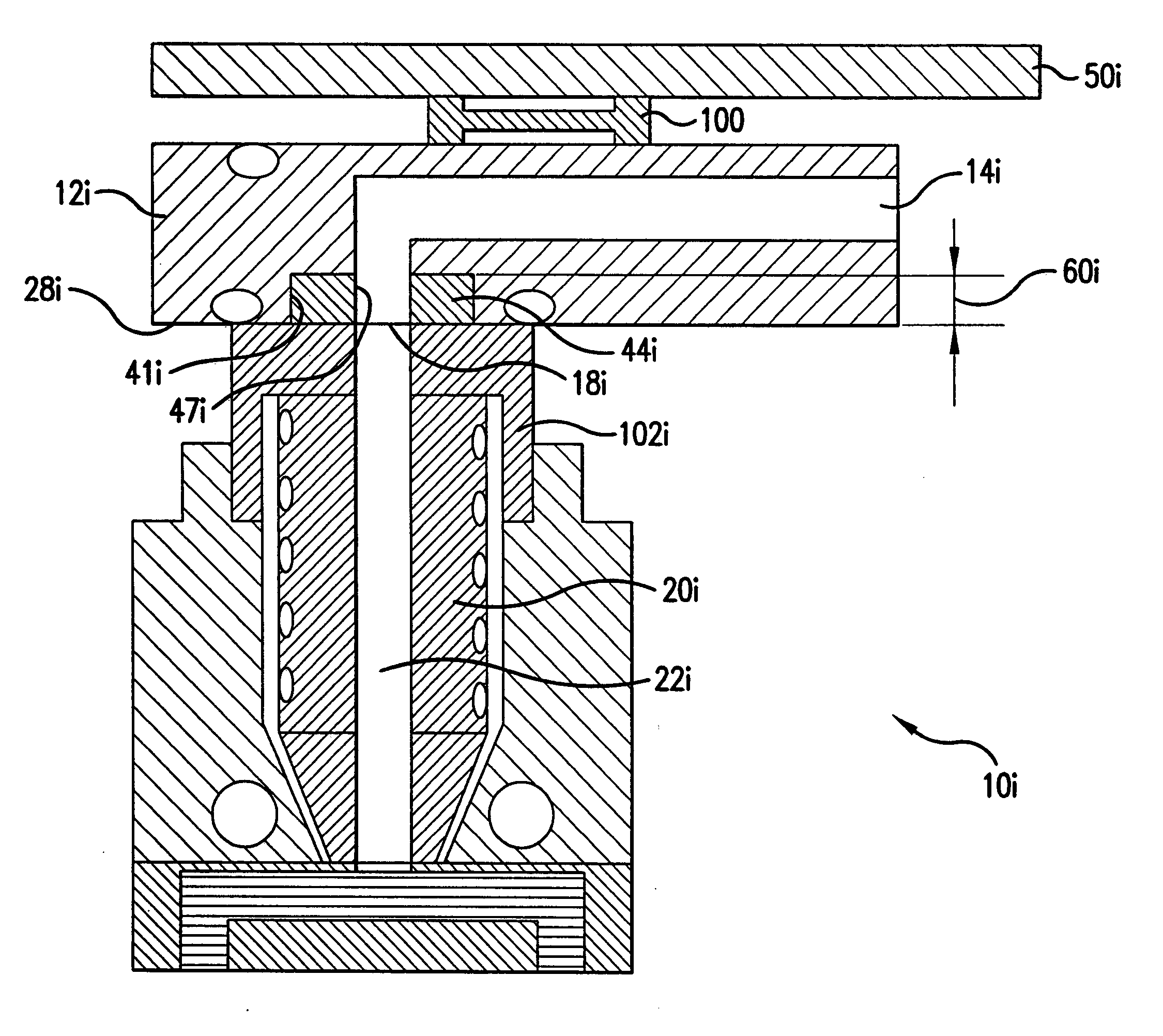
Figure 1 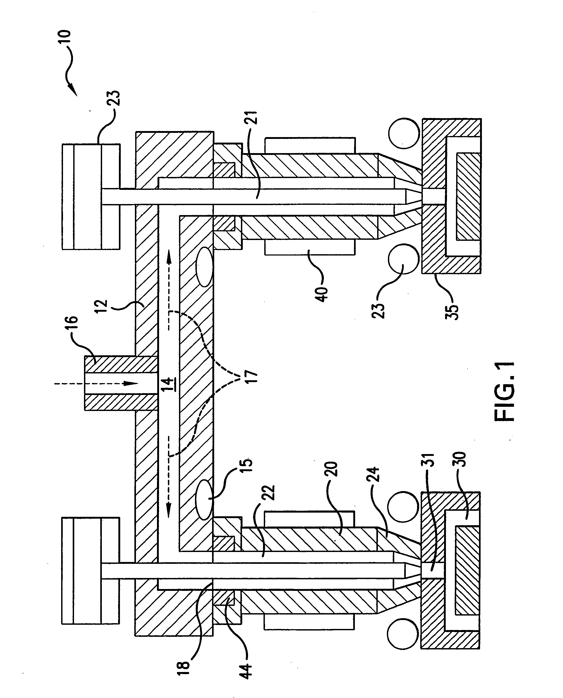
Figure 2 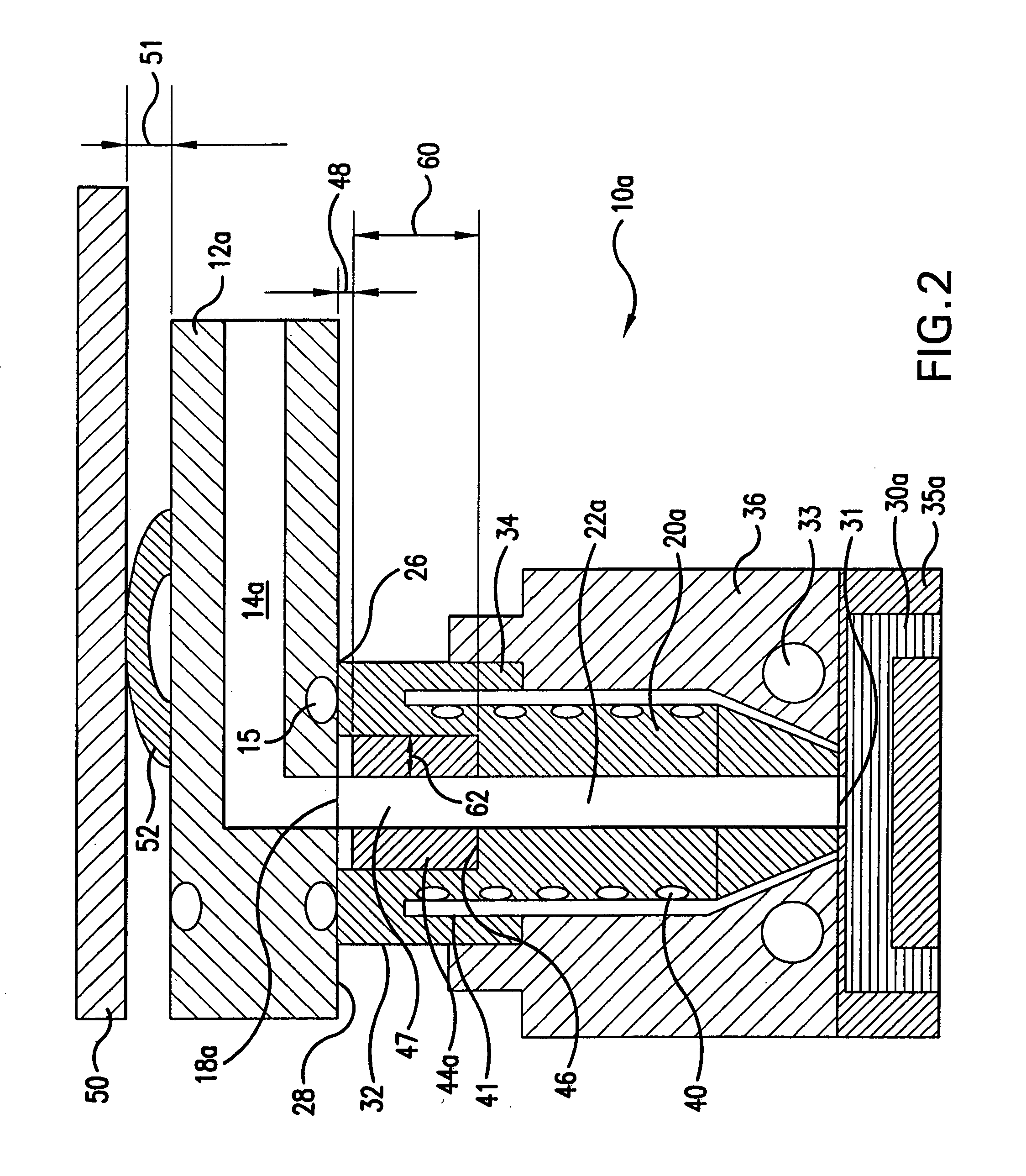
Figure 3
Abstract
Description
FIELD OF THE INVENTION
[0001] The present invention relates generally to an injection molding apparatus and, in particular, to an improved seal between a manifold and a nozzle. BACKGROUND OF THE INVENTION
[0002] A common problem associated with hot runner injection molding systems is the leaking of molten plastic that can occur between the manifold and the nozzle. Leaking is typically caused by operation of the hot runner injection molding system outside of the designated operating window. There are many different nozzle designs of the prior art that attempt to stop leakage from occurring.
[0003] A pair of spacers located between a manifold and a cover plate or a hot runner plate, such as disclosed in U.S. Pat. Nos. 6,309,207, 6,062,846 and U.S. Patent Application No. 2001 / 0011415, apply a contact pressure between the nozzle body melt channel and the manifold melt channel to achieve a seal therebetween. The spacers are arranged in series with a first spacer abutting the manifold and...
Examples
Embodiment Construction
[0039] Referring now to FIG. 1, an injection molding apparatus is generally indicated by reference numeral 10. The injection molding apparatus comprises a manifold 12 having a manifold channel 14 extending therethrough. A manifold bushing 16 that is located at an inlet of the manifold channel 14 receives a melt stream of moldable material from a machine nozzle (not shown). The melt stream flows through the manifold channel 14 and is delivered to outlets 18, as indicated by the arrows 17. Manifold heaters 15 are provided in the manifold 12 to maintain the melt stream at a desired temperature.
[0040] Nozzles 20 are located between the manifold 12 and respective mold cavities 30, which are formed in mold cavity plates 35. Each nozzle 20 includes a nozzle channel 22 for receiving the melt stream from the respective manifold outlet 18 and delivering the melt stream to the respective mold cavity 30. Mold gates 31 are provided at the entrance to the mold cavities 30, adjacent tips 24 of th...