
Sensor device and method
Patent Information
- Authority / Receiving Office
- US · United States
- Current Assignee / Owner
- Publication Date
- 2006-04-06
- Estimated Expiration
- Not applicable · inactive patent
Smart Images
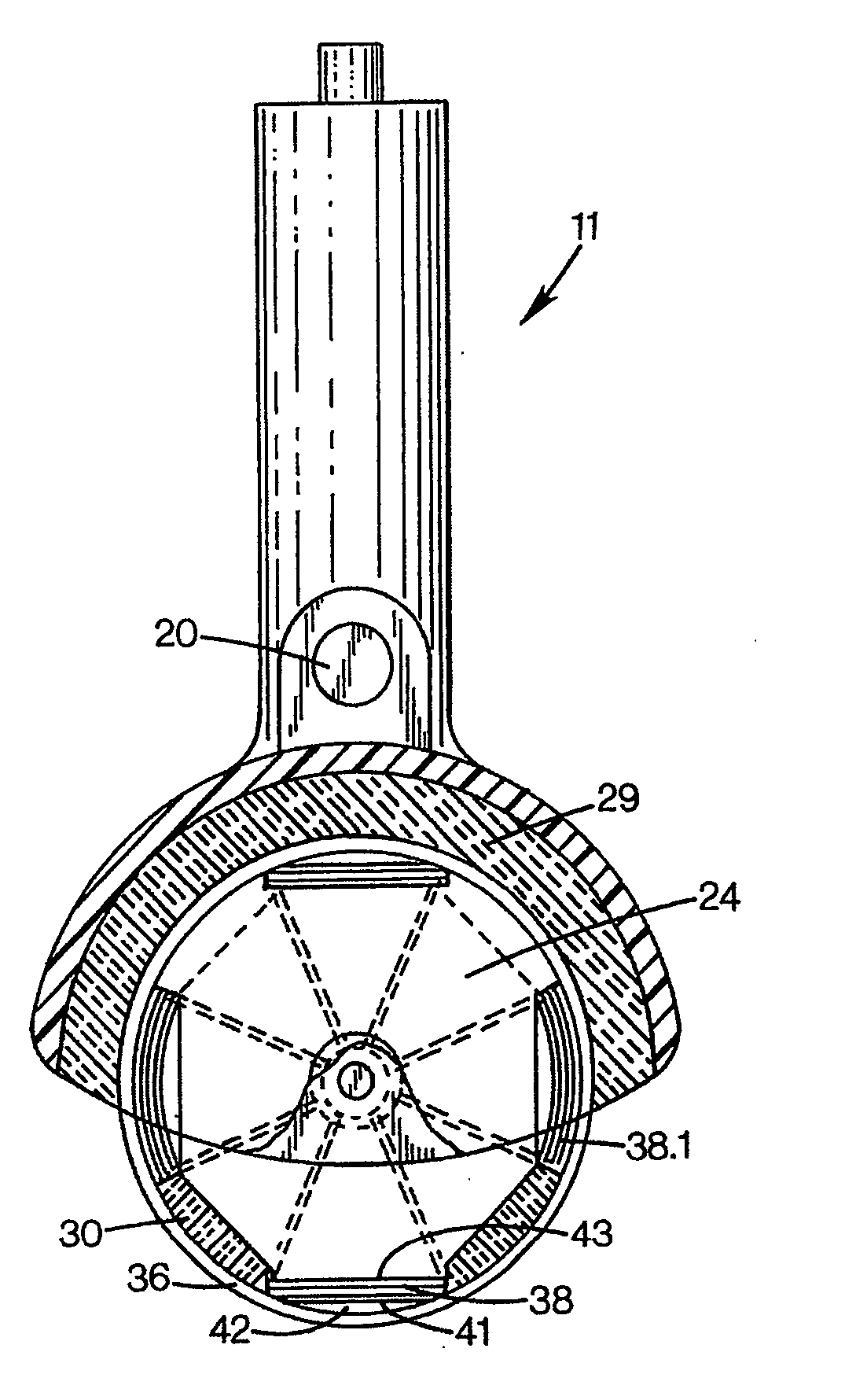
Figure 1 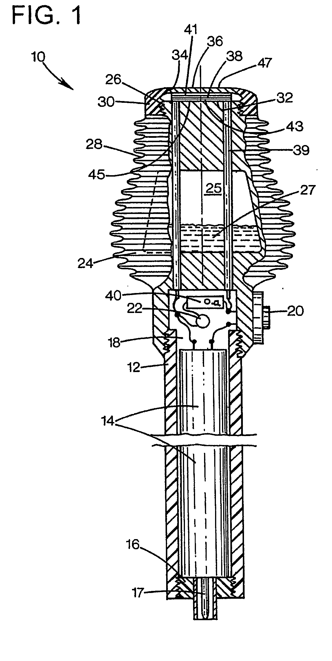
Figure 2 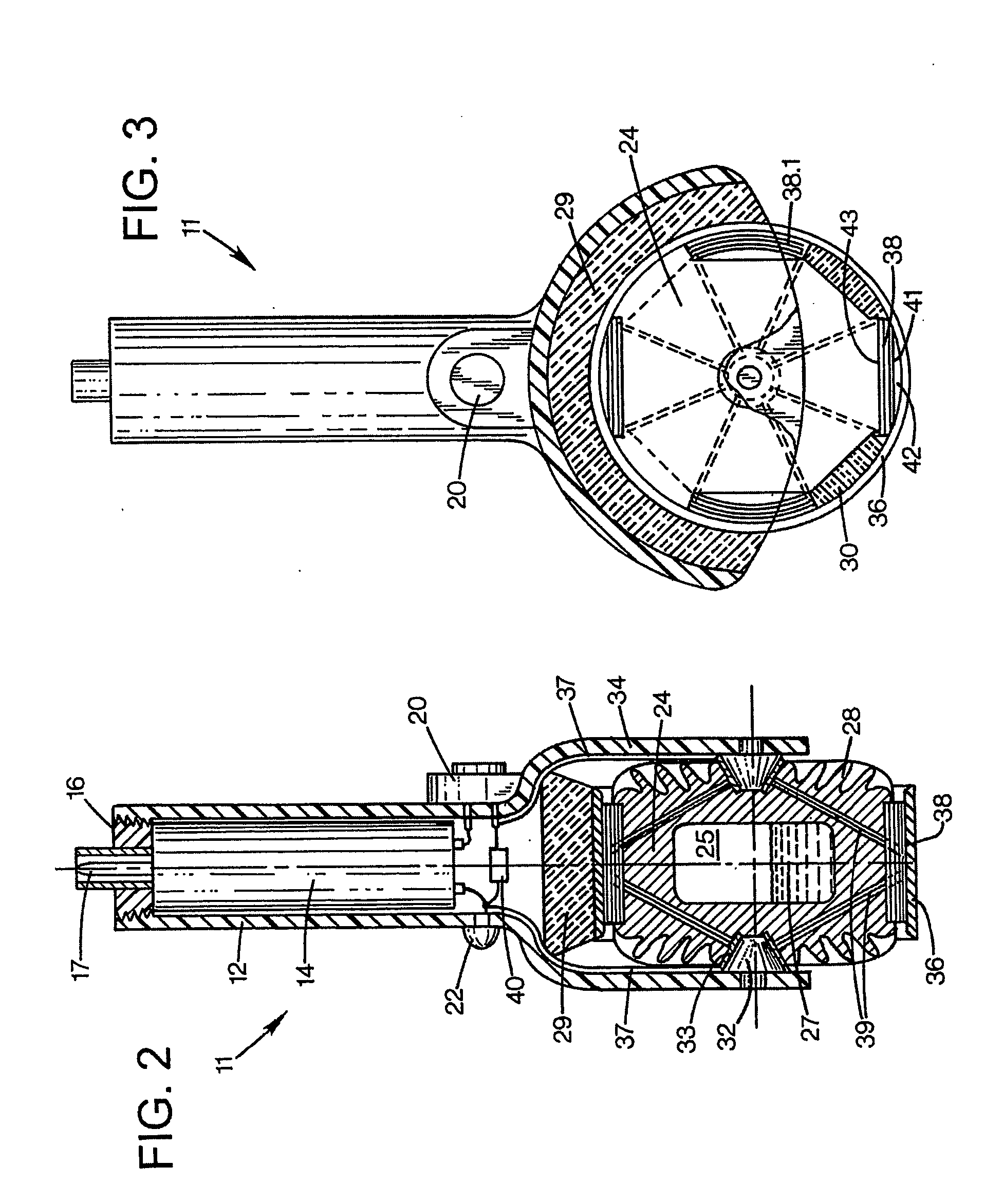
Figure 3
Abstract
Description
TECHNICAL FIELD
[0001] The present invention relates to a cooled sensor device and a method of using the device. BACKGROUND AND SUMMARY OF THE INVENTION
[0002] Physicians / surgeons and other medical professionals often need to administer anesthetics before conducting surgery and other operations. However, it is sometimes difficult to know how effective the anesthetic drugs are and the size of the area affected. For example, when administering anesthetics to the spine it is often important to determine how high up on the spine the anesthetics have traveled. Some medical professionals test this by applying ice cubes or cold rubber alcohol to skin along the spine and the patient is asked whether the ice can be felt or not. This method is messy and unreliable.
[0003] It is also necessary for the medical professional to repeatedly go between a freezer and the patient since the ice melts at room temperature. Other professionals pinch the patient with a tool or use needles. These methods ar...
Examples
Embodiment Construction
[0013] With reference to FIG. 1, a first embodiment of the elongate sensor device 10 is shown that may be used for sensing nerve reactions of a patient by using a cold element, as explained below. The cooling element may hold a constant temperature of about −5 to −15 C or any other suitable temperature range. Only a small cooling power is required and it is often sufficient to use one peltier element. However, even lower temperatures can be accomplished by applying two peltier elements on top of each other.
[0014] The device 10 is useful for determining the area affected by, for example, anesthesia on the body of the patient. The device 10 has an elongate housing 12 that may contain a power source 14, such as batteries, held in place by a removable lid 16. A coupling 17 is arranged in the lid 16 and the coupling 17 is suitable for connecting a battery charger to the battery. A mid-portion 18 of the housing 12 has a switch 20 for turning on and off the device 10. The housing 12 may a...