
Channel emulating device
Patent Information
- Authority / Receiving Office
- US · United States
- Current Assignee / Owner
- Publication Date
- 2007-06-14
- Estimated Expiration
- Not applicable · inactive patent
Smart Images
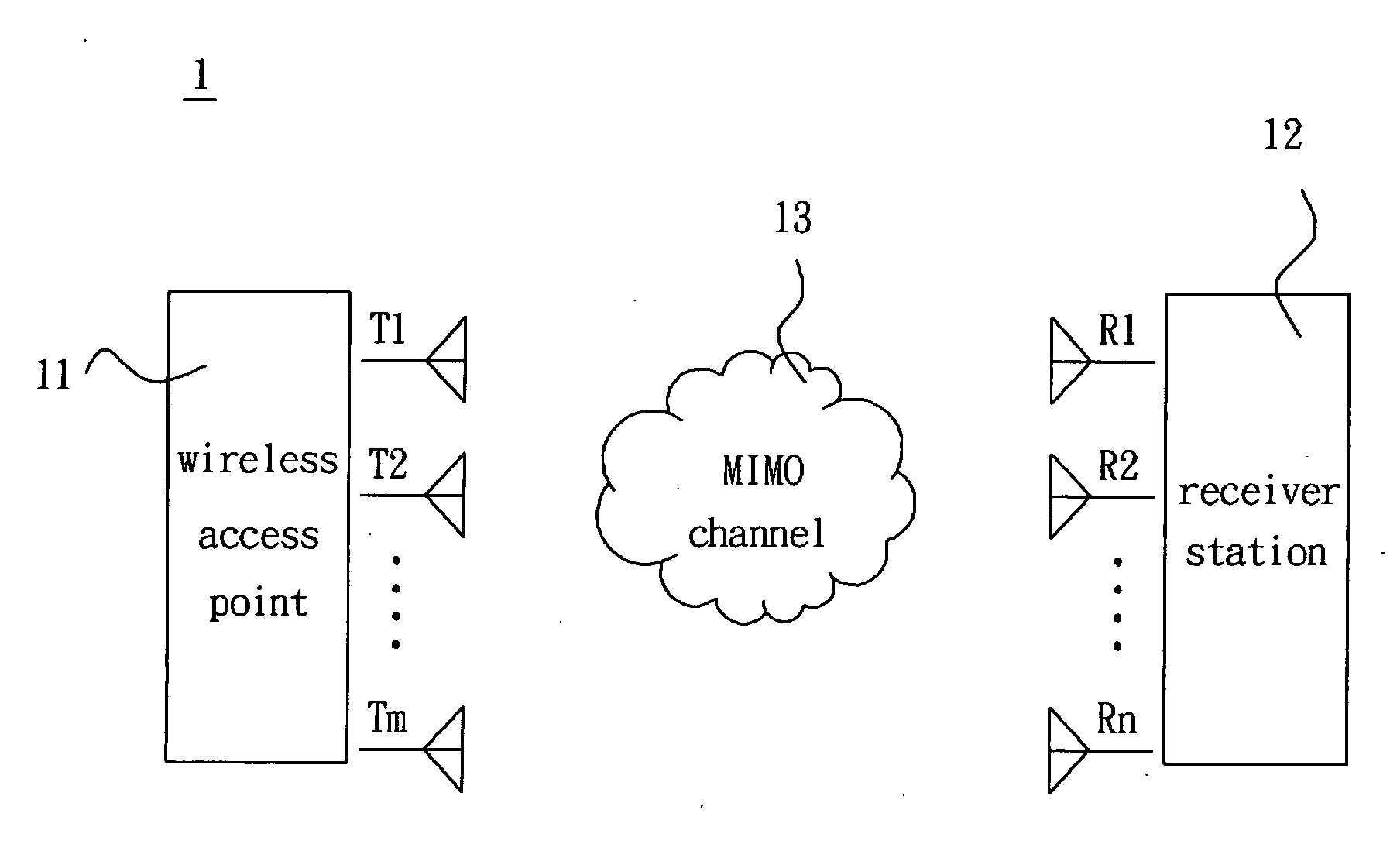
Figure 1 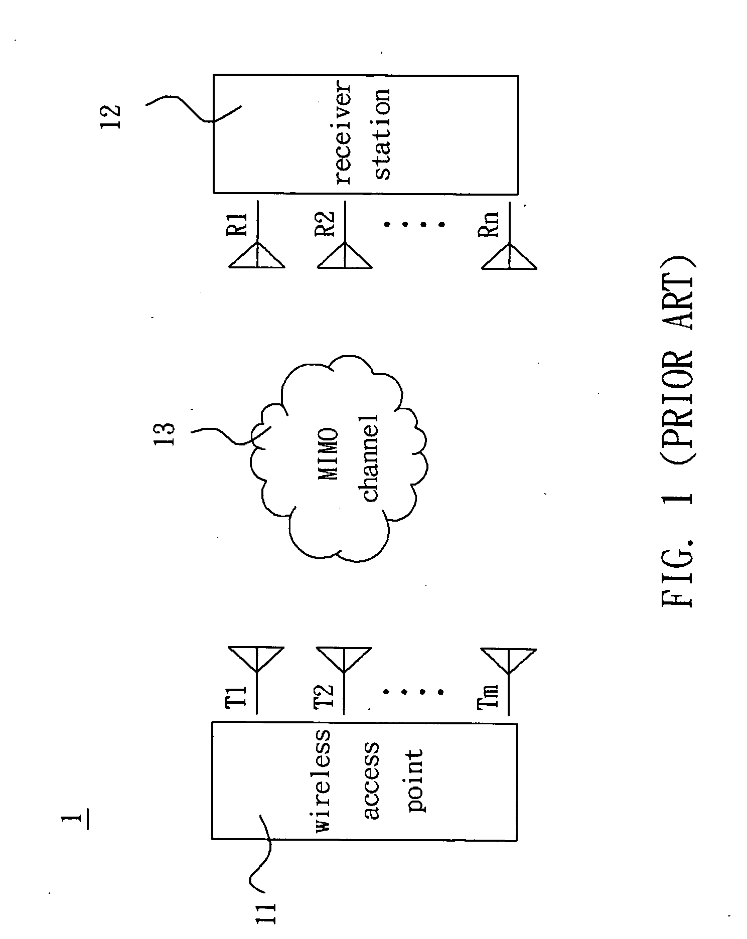
Figure 2 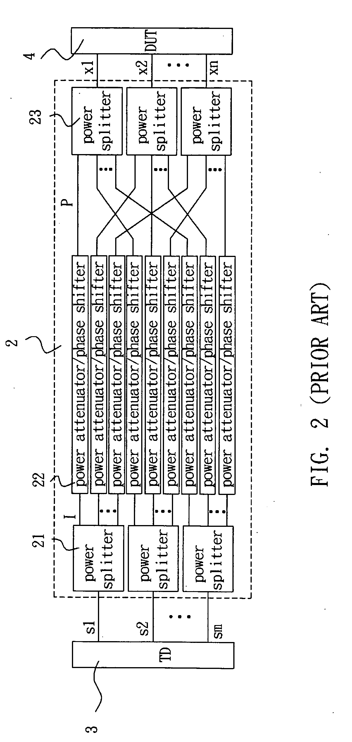
Figure 3
Abstract
Description
BACKGROUND OF THE INVENTION
[0001] 1. Field of Invention
[0002] The present invention relates to an emulating device, and more particularly, to a channel emulating device adapted to multiple-input multiple-output (MIMO) transmission systems.
[0003] 2. Related Art
[0004] Accompanying to the progress of the technology, the wireless transmission-technology has been continuously developed and has tightly combined with the daily life. The electronic products such as mobile phones, personal digital assistants (PDAs), personal computers, and the like have brought a more convenient environment. In the age of the mass information flow, the demand on the-wireless transmission gets higher and higher.
[0005] A wireless communication system having a higher efficiency and a higher capability are needed in order to enhance the information transmission quality and the signal covering range and to implement the reliable and stable transmission. A MIMO transmission system is one of the wireless commu...
Examples
first embodiment
[0018] As shown in FIG. 3, a channel emulating device according to the present invention emulates such as 4×4 wireless transmission systems.
[0019] In this embodiment, the channel emulating device 5 is disposed between a testing device TD and a device-under-test DUT. The testing device TD has a wireless access point (AP)(not shown). The testing device TD generates a first input signal S1 and three second input signals S2, S3 and S4 and transmits the signals S1 to S4 to the channel emulating device 5. The device-under-test DUT has an Ethernet adapter and a computer (not shown). The device-under-test DUT receives a first output signal X1 and three second output signals X2, X3 and X4. The channel emulating device 5 includes a first choosing module 51, a first signal integrating module 52, a first parameter adjusting module 53, a second parameter adjusting module 54, a second choosing module 55, a second signal integrating module 56 and a third choosing module 57.
[0020] The first choosi...
second embodiment
[0037] As shown in FIG. 4, a channel emulating device according to the present invention emulates such as 2×2 wireless transmission systems.
[0038] In this embodiment, the channel emulating device 6 is disposed between a testing device TD and a device-under-test DUT. The testing device TD generates a first input signal S1 and a second input signal S2 and transmits the signals S1 and S2 to the channel emulating device 6. The device-under-test DUT receives a first output signal X1 and a second output signal X2. The channel emulating device 6 includes a first choosing module 61, a first signal integrating module 62, a first parameter adjusting module 63, a second parameter adjusting module 64, a second choosing module 65, a second signal integrating module 66, a third choosing module 67 and a control module 68. The connections, properties and functions of the above-mentioned modules are the same as those of the first embodiment, and detailed descriptions thereof will be omitted. In this...