
Relay apparatus, relay method, and relay program
a relay and relay technology, applied in the field of relay apparatus, relay method, relay program, can solve the problems of insufficient securing a stable transmission quality, insufficient above-described conventional method, and inability to provide stably and efficiently utilize limited bandwidth, so as to achieve the effect of stably and efficiently utilizing limited bandwidth
Patent Information
- Authority / Receiving Office
- US · United States
- Patent Type
- Applications(United States)
- Current Assignee / Owner
- Publication Date
- 2008-02-14
- Estimated Expiration
- Not applicable · inactive patent
Smart Images
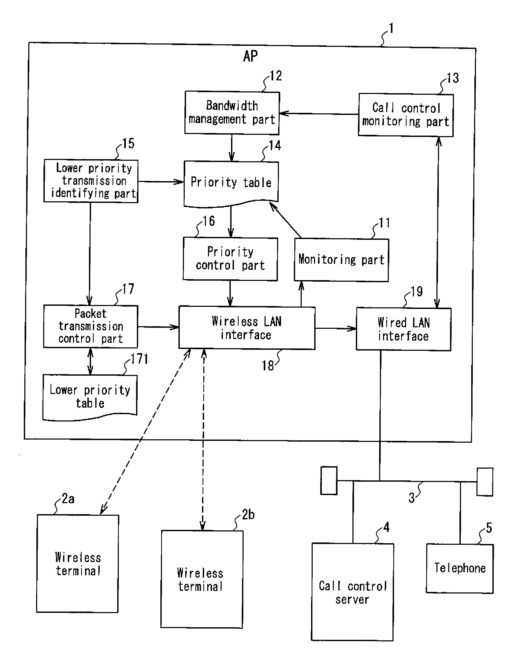
Figure 1 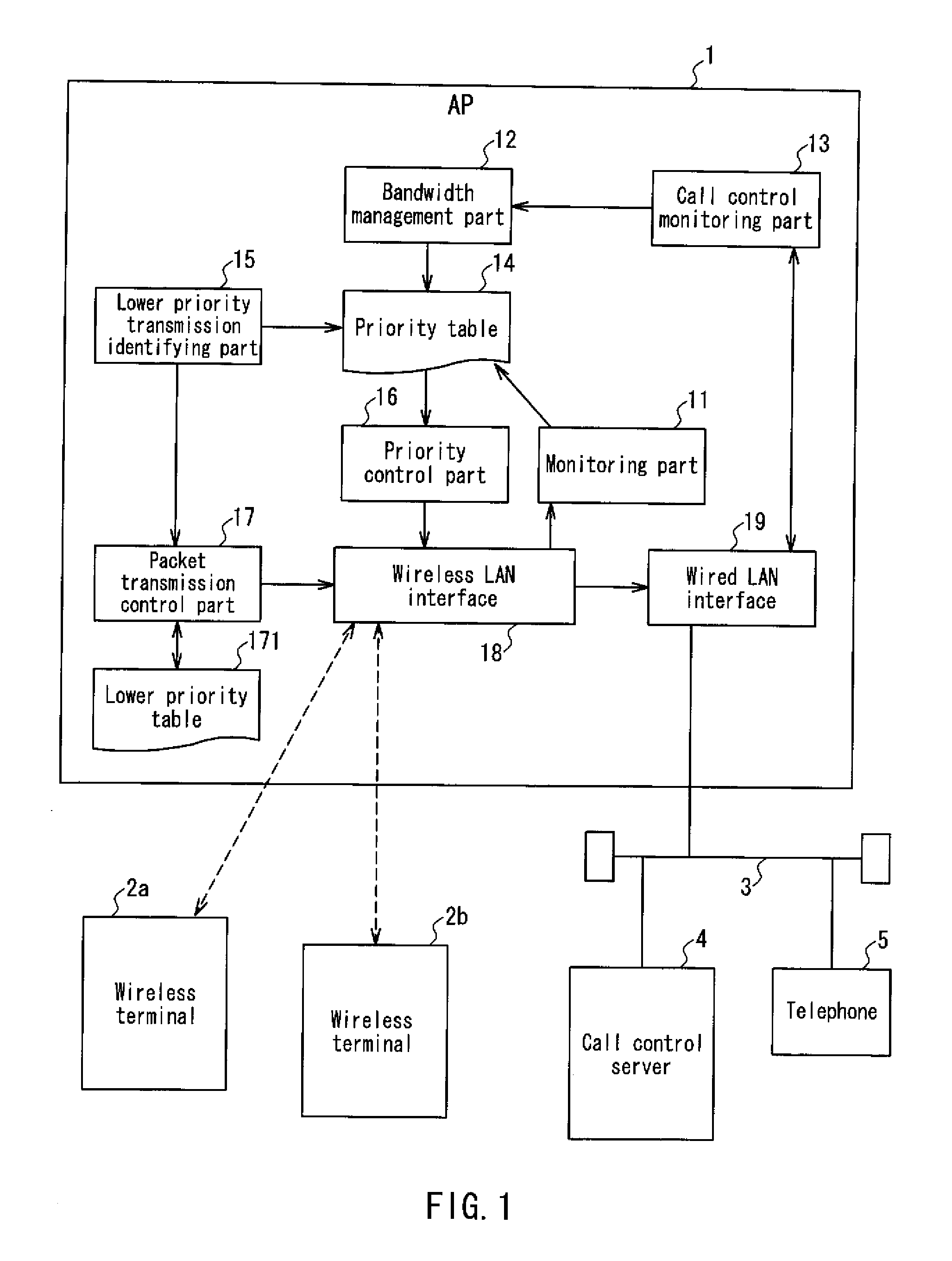
Figure 2 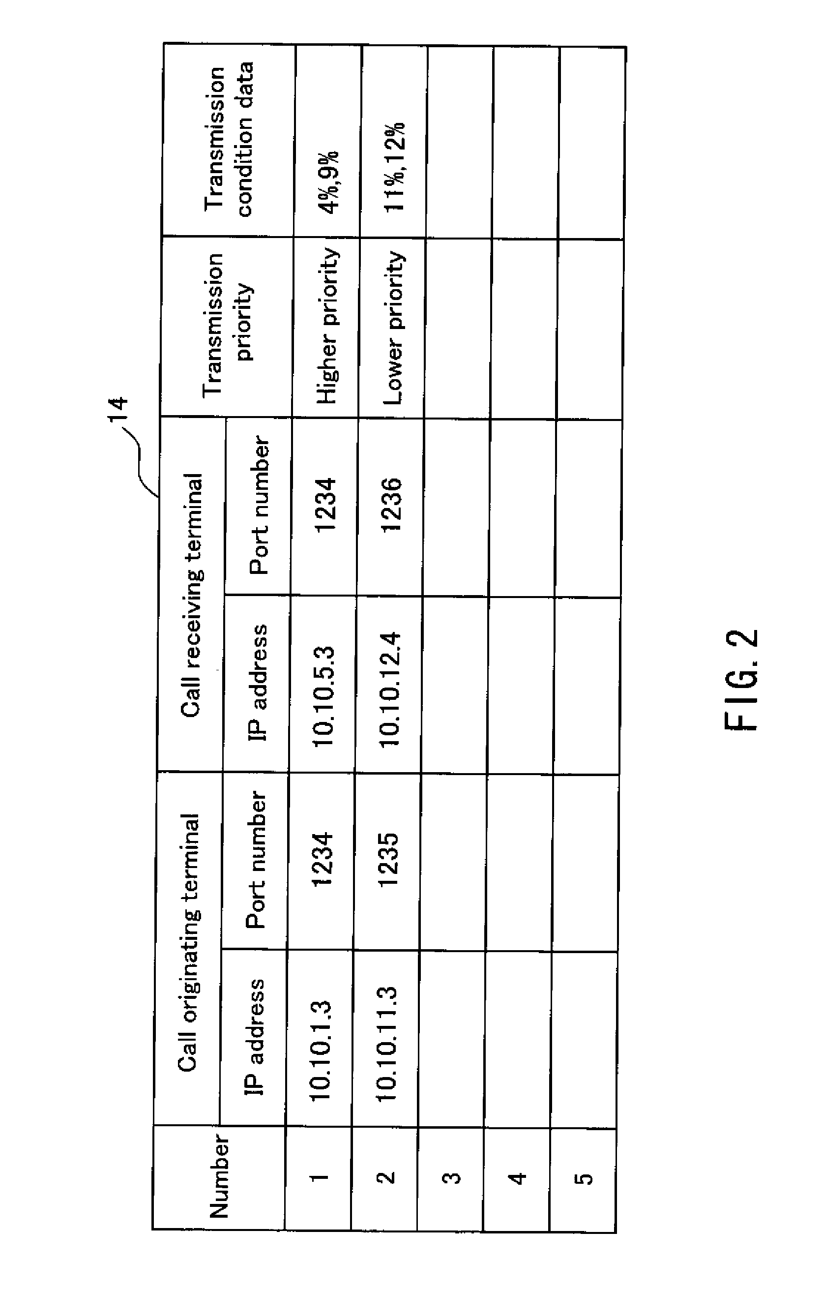
Figure 3
Abstract
Description
BACKGROUND OF THE INVENTION
[0001] 1. Field of the Invention
[0002] The present invention relates to a relay apparatus for relaying transmission among a plurality of wireless terminals in a coverage area of the relay apparatus with a limited bandwidth, like an access point in a wireless LAN (local area network).
[0003] 2. Description of Related Art
[0004] Recently, for example, as in an IP telephone via a wireless LAN, a wireless terminal that performs a telephone conversion via radio transmission has become widespread. The wireless terminal that performs a telephone call via radio transmission enables a telephone call with a terminal on a partner side by performing radio transmission with a relay apparatus (e.g., an access point of a wireless LAN, etc.). In such a transmission form, mobile terminals are present in a coverage area of a relay apparatus, whereby simultaneous telephone calls by the mobile terminals occur. In this case, those mobile terminals share a transmission bandwidth avai...
Examples
embodiment 1
[0038]The present embodiment is an exemplary embodiment in the case where a relay apparatus is a wireless LAN access point (hereinafter referred to as AP). The wireless LAN is within the specification of a short-haul wireless network according to the IEEE 802.11 standard. FIG. 1 is a functional block diagram showing a configuration of the AP according to the present embodiment, together with an overall configuration of an entire communication system incorporating the foregoing AP. The communication system shown in FIG. 1 is, for example, a system that enables telephone calls over wireless IP telephones utilizing the wireless LAN.
[0039]The communication system shown in FIG. 1 includes an AP 1, a call control server 4, and a telephone 5 connected with a wired LAN 3, and wireless terminals 2a and 2b in a coverage area of the AP1. The wireless terminals 2a and 2b and the telephone 5 have functions as IP telephone terminals. It should be noted that the number of the AP connected with the...
embodiment 2
[0086]The present embodiment is a modification of the operation of the AP 1 according to Embodiment 1. FIG. 7 shows a data configuration of a priority table 14a according to the present embodiment. The priority table 14a shown in FIG. 7 has the same configuration as that of the priority table 14 (see FIG. 2) shown as an example according to Embodiment 1 except that a column for storing data relating to the “Duration of degradation” is added. The duration of degradation is a time period while a transmission is kept continuously in a state under a degraded transmission condition. The data representing the duration of degradation are not necessarily represented in units of hour, minute, second, or the like, but may assume values that enable comparison with the other transmissions.
[0087]Further, Embodiment 1 is described by referring to an example in which each transmission priority in the priority table 14 is recorded with data representing either one of two levels, “Higher priority” a...
embodiment 3
[0095]FIG. 9 is a functional block diagram illustrating a configuration of an AP according to the present embodiment together with an overall configuration of the entire communication system incorporating the foregoing AP. Among the functional blocks shown in FIG. 9, those identical to the functional blocks shown in FIG. 1 are designated by the same reference numerals and descriptions of the functional blocks are omitted. An AP 1a shown in FIG. 9 has the same configuration as that of the AP 1 shown in FIG. 1 except that an adjacent AP information obtaining part 31 is added. Besides, not only the AP 1a but also the AP 1b are connected to the wired LAN 3. The AP 1a and the AP 1b are provided adjacent to each other at a distance such that radio waves transmitted from them interfere with each other. In the coverage area of the AP 1b, a wireless terminal 2c exists. The internal configuration of the AP 1b is identical to that of the AP 1a.
[0096]Operations of the AP 1a and the AP 1b accor...