
Valve for a pressurized dispensing container
Patent Information
- Authority / Receiving Office
- US · United States
- Current Assignee / Owner
- Publication Date
- 2008-02-21
Smart Images
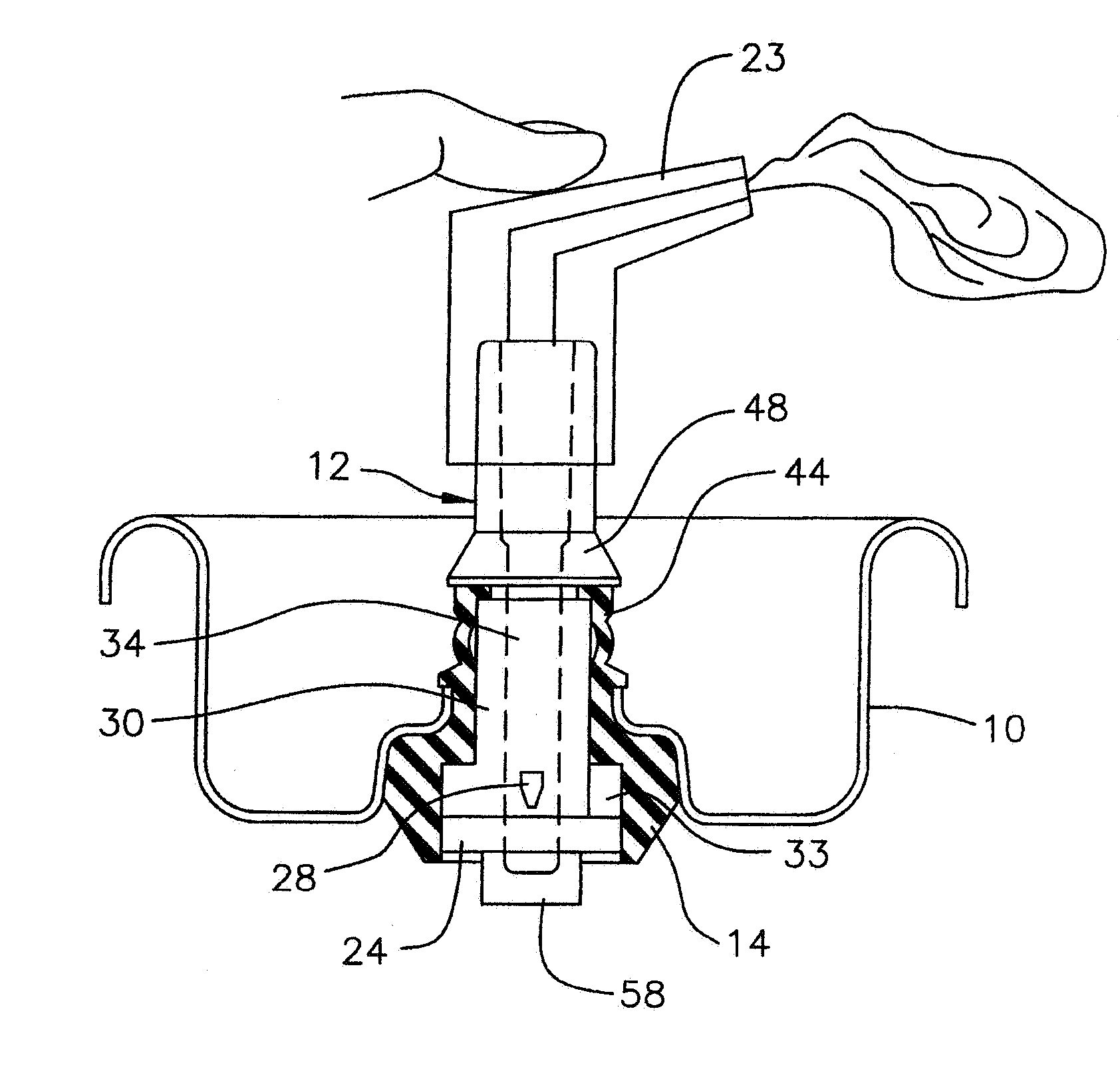
Figure 1 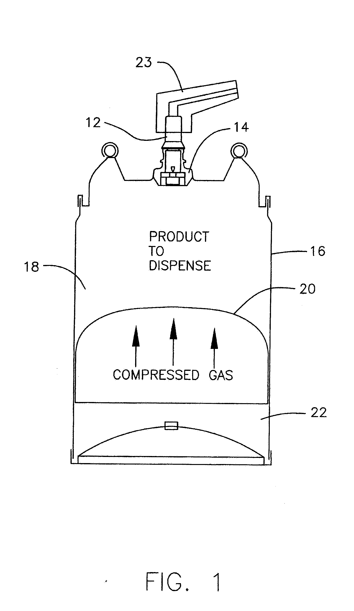
Figure 2 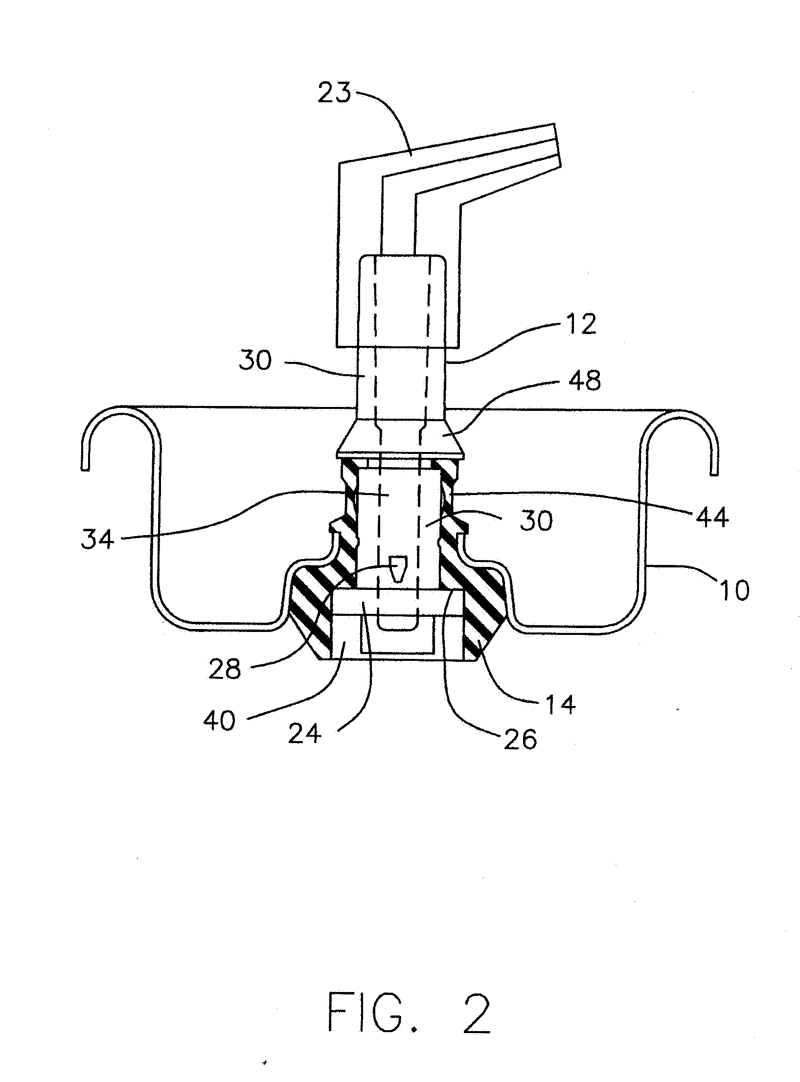
Figure 3
Abstract
Description
REFERENCE TO RELATED APPLICATIONS
[0001] This application is a continuation-in-part of Ser. No. 11 / 334,716 filed Jan. 18, 2006, which in turn is a continuation-in-part of Ser. No. 10 / 882,625 filed Jun. 30, 2004, which in turn is a continuation of Ser. No. 10 / 816,969 filed Apr. 2, 2004, now abandoned, which in turn is a continuation of Ser. No. 10 / 285,238 filed Oct. 31, 2002, now abandoned; the entire disclosures of which are hereby incorporated by reference. BACKGROUND OF THE INVENTION
[0002] This invention relates to a valve design for use in dispensing product from a pressurized container and more particularly to a valve whose design provides user control over the dispensing rate. This is particularly valuable where pressure in the container is developed from a gas, such as pressurized air or pressurized nitrogen, in which the pressure decreases as product is dispensed.
[0003] Applicant's U.S. Pat. No. 5,785,301 and U.S. Pat. No. 6,425,503 and U.S. Pat. No. 6,340,103 are represent...
Examples
Embodiment Construction
[0037] The FIGs. illustrate a single embodiment. As shown in FIG. 2, the three piece valve assembly is constituted by a mounting cup 10, a movable valve element 12 and a resilient annular sealing grommet 14. The valve element 12 has a button 24 which fits in a recess 40 in the base of the grommet 14.
[0038] The mounting cup 10 performs a known function of mounting the valve assembly on top of the container 16 in which the product to be dispensed is contained. The product 18 to be dispensed is above the piston 20 which acts as a barrier between the product 18 and the gas under pressure in the lower chamber 22. The gas under pressure causes the piston 20 to apply pressure to the product 18. A piston 20 barrier is shown. But as is known in the art a collapsible bag barrier can be employed. A hand operated actuator 23 is mounted on top of the valve element 12.
[0039] The valve has a closed state in which the valve element 12 is in an upward position where a button 24 at the base of the ...