
Method and Device for the Combustion of Hydrogen in a Premix Burner
Patent Information
- Authority / Receiving Office
- US · United States
- Current Assignee / Owner
- Publication Date
- 2008-04-24
- Estimated Expiration
- Not applicable · inactive patent
Smart Images
Figure 1 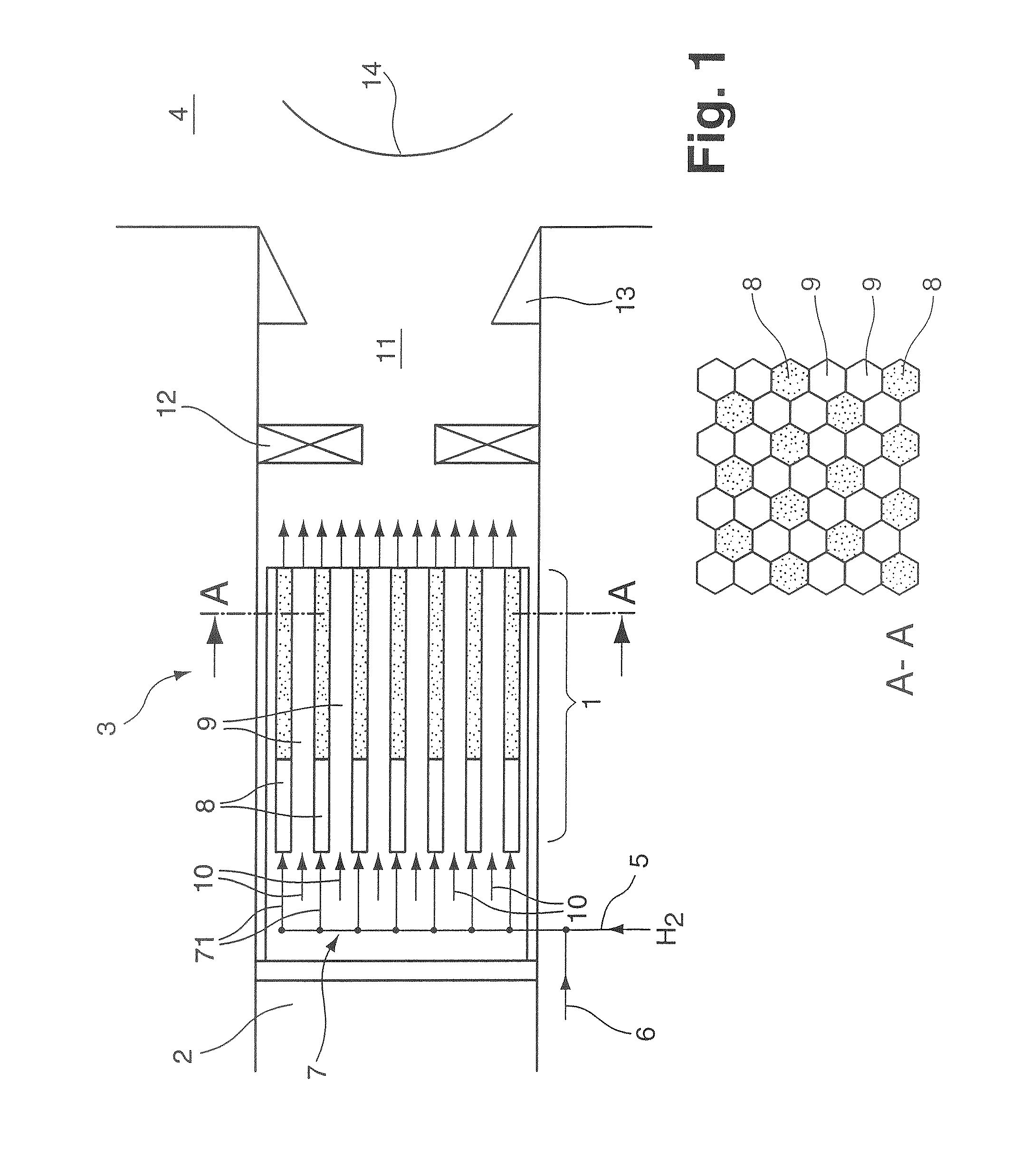
Figure 2 
Figure 3
Abstract
Description
[0001] This application is a Continuation of, and claims priority under 35 U.S.C. § 120 to, International application no. PCT / EP2006 / 060518, filed 7 Mar. 2006, and claims priority therethrough under 35 U.S.C. § 119 to Swiss application no. 00506 / 05, filed 23 Mar. 2005, the entireties of both of which are incorporated by reference herein.BACKGROUND
[0002] 1. Field of Endeavor
[0003] The invention relates to a method and a device for producing an ignitable fuel-air mixture, the fuel fraction of which consists of hydrogen or of a gas mixture containing hydrogen and which is burnt in a burner arrangement for driving a thermal engine, in particular a gas turbine plant.
[0004] 2. Brief Description of the Related Art
[0005] Motivated by the virtually worldwide effort to reduce the emission of greenhouse gases into the atmosphere, not least set down in what is known as the Kyoto Protocol, the emission of greenhouse gases which is to be expected in 2010 is to be reduced to the same level as ...
Examples
Embodiment Construction
[0036]FIG. 1 provides a diagrammatic longitudinal sectional illustration through a burner arrangement with a catalyzer unit 1, which is arranged in the flow inlet region 2 of the burner 3 at which a combustion chamber 4 is provided downstream. To operate the burner arrangement, illustrated in FIG. 1, with hydrogen as fuel, a fuel supply line 5, and an air supply line 6 are provided, which issue jointly into an infeed 7. The infeed 7 has connecting lines 71 issuing into passage ducts 8 which project axially through the catalyzer unit 1. The catalyzer unit itself includes a carrying structure which is pierced with a multiplicity of passage ducts and in which the multiplicity of passage ducts are arranged in a matrix-like manner, preferably in each case in a hexagonal honeycomb pattern arrangement. A diagrammatic cross section through the hexagonal honeycomb structure is illustrated in the sectional illustration A-A. The passage ducts piercing the carrying structure of the catalyzer un...