
Photography apparatus and photography method
Patent Information
- Authority / Receiving Office
- US · United States
- Current Assignee / Owner
- Publication Date
- 2010-04-01
- Estimated Expiration
- Not applicable · inactive patent
Smart Images
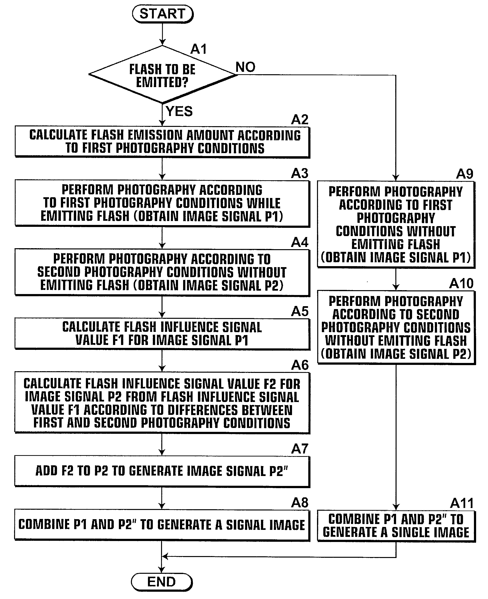
Figure 1 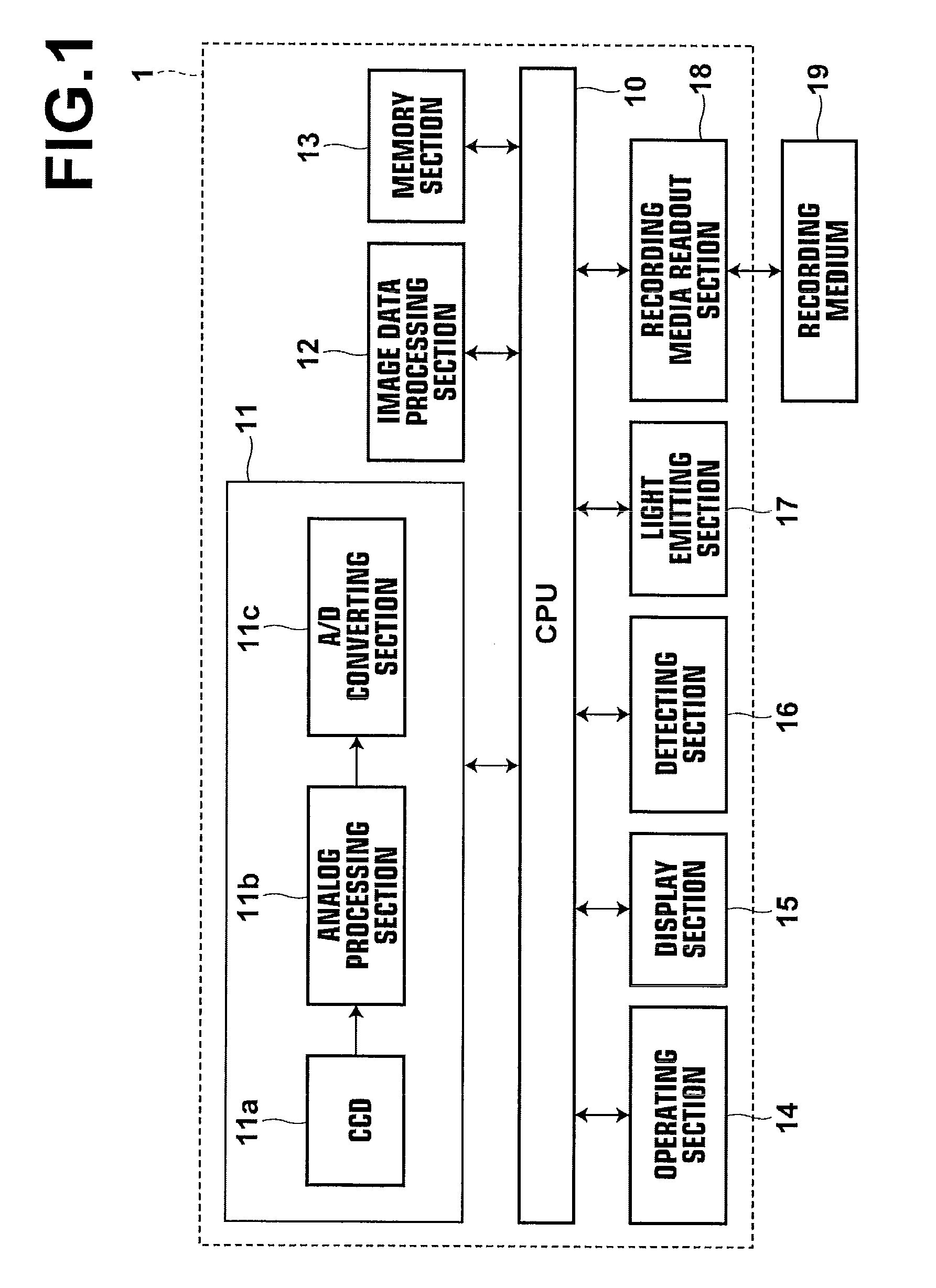
Figure 2 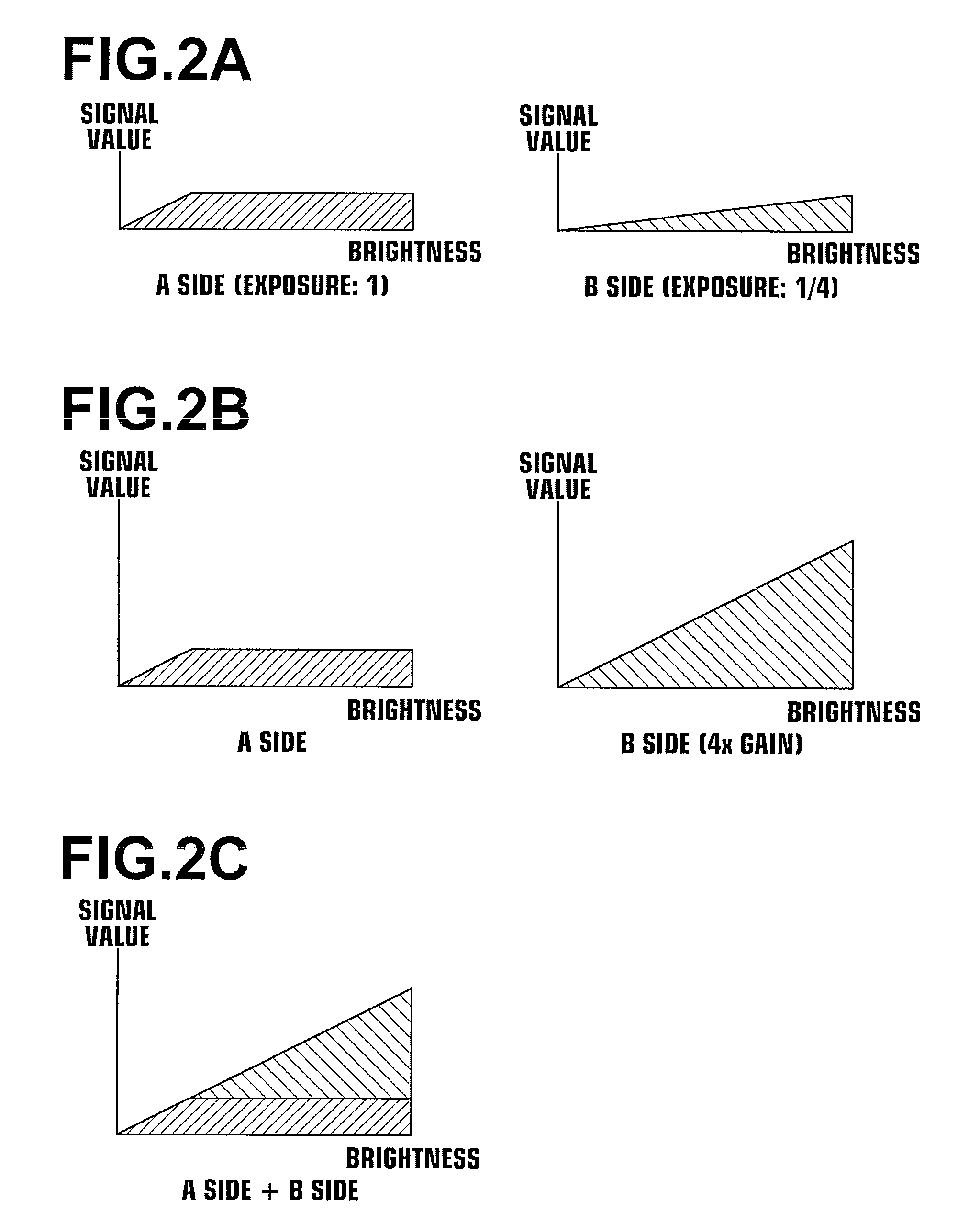
Figure 3
Abstract
Description
BACKGROUND OF THE INVENTION
[0001] 1. Field of the Invention
[0002] The present invention is related to a photography apparatus and a photography method that perform a plurality of photography operations under different photography conditions, then processes the image signals obtained by the photography signals to obtain various image signals.
[0003] 2. Description of the Related Art
[0004] CCD's, which are imaging means employed in digital cameras, have narrower dynamic ranges than silver salt film. Therefore, overexposure and underexposure are likely to occur in images photographed by digital cameras. For this reason, there are known techniques for obtaining image signals having expanded dynamic ranges that exhibit favorably reproduction properties over a wide range from high brightness to low brightness. In these techniques, imaging is performed with different exposure conditions to obtain an image signal that represents an image having a large amount of data toward the high brightness s...
Examples
first embodiment
[0074]Hereinafter, embodiments of the present invention will be described with reference to the attached drawings. FIG. 1 is a schematic block diagram that illustrates the construction of a digital camera 1, to which a photography apparatus according to the present invention is applied.
[0075]As illustrated in FIG. 1, the digital camera 1 of the first embodiment is constituted by: a CPU 10; an imaging section 11; an image signal processing section 12; a memory section 13; an operating section 14; a display section 15; a detecting section 16; a light emitting section 17; and a recording media readout section 18.
[0076]The imaging section 11 is configured to perform a plurality of photography operations with different photography conditions with respect to the same subject, and to obtain a plurality of image data sets corresponding to each of the photography operations. The imaging section 11 is equipped with: a lens group (not shown); a lens driving section (not shown); a CCD 11a that ...
second embodiment
[0103]The imaging section 11 of the second embodiment performs continuous high speed photography with different exposure times, to obtain an A side image signal, mainly for obtaining data toward the low brightness side, and a B side image signal with a smaller amount of exposure than the A side image signal, mainly for obtaining data toward the high brightness side.
[0104]When photography is initiated, subject data and subject field data are detected by various sensors of the detecting section 16. The CPU 10 sets how much the dynamic range of the image data set to be ultimately obtained is to be expanded from that of an image data set which is obtained by standard photography. Further, the CPU 10 judges whether flash is to be emitted, based on the subject data and the subject field data detected by the detecting section 16 (step B1).
[0105]In the case that it is judged that flash is not to be emitted at step B1, photography is performed according to a non flash emission photography me...
third embodiment
[0114]The imaging section 11 of the third embodiment employs a CCD, in which a plurality of first light receiving elements and a plurality of second light receiving elements, which are capable of being controlled and driven independent from each other and are arranged in a predetermined arrangement. The CCD is utilized to obtain an A side image signal, mainly for obtaining data toward the low brightness side, and a B side image signal with a smaller amount of exposure than the A side image signal, mainly for obtaining data toward the high brightness side. Note that the sensitivities of the first light receiving elements and the second light receiving elements are the same. A first photography operation (to obtain the A side image signal) and a second photography operation (to obtain the B side image signal) can be performed simultaneously with different exposures, by performing the photography operations with different exposure times by employing electronic shutters.
[0115]When photo...