
System and method for pain reduction during skin puncture and breakable tip therefor
Patent Information
- Authority / Receiving Office
- US · United States
- Current Assignee / Owner
- Publication Date
- 2012-02-02
Smart Images
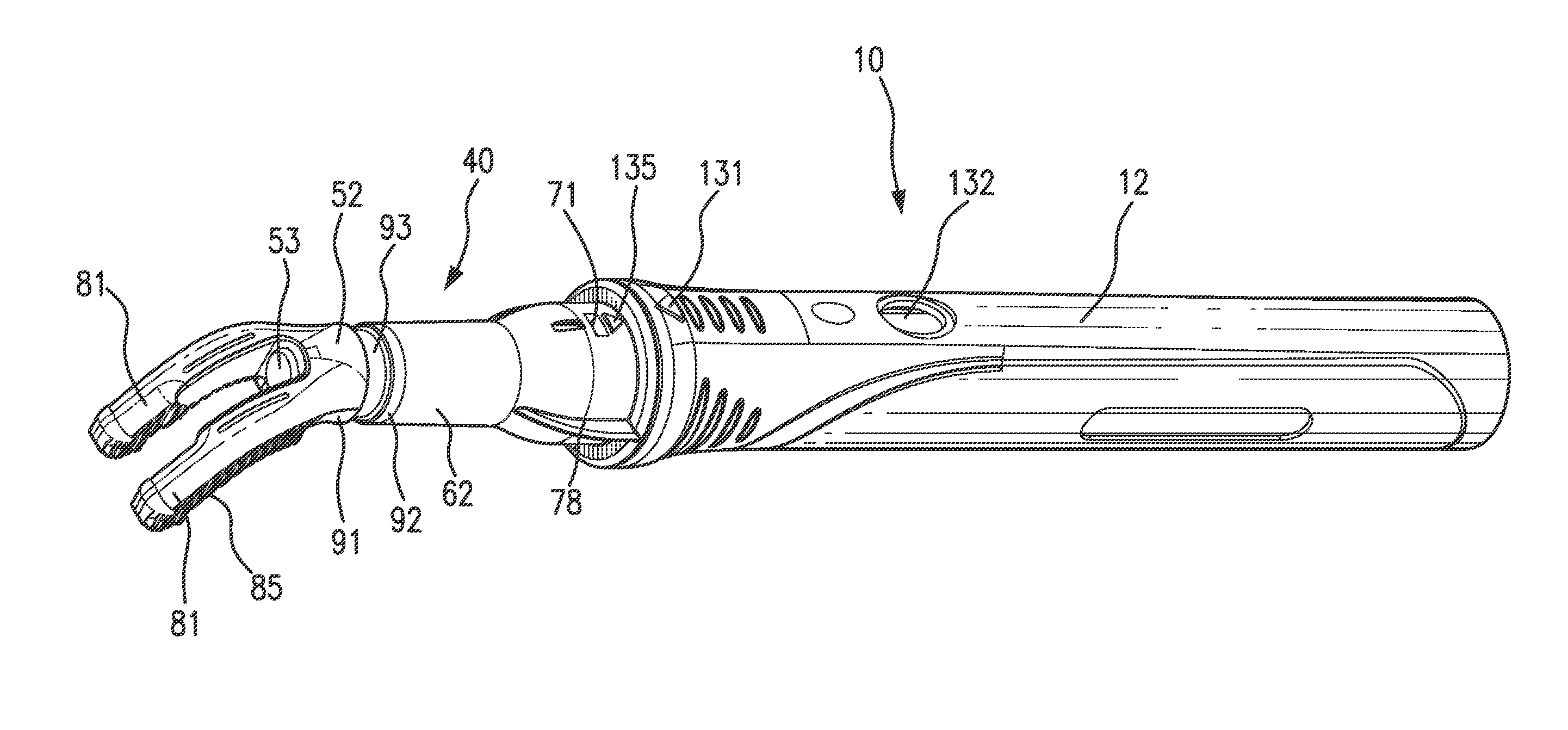
Figure 1 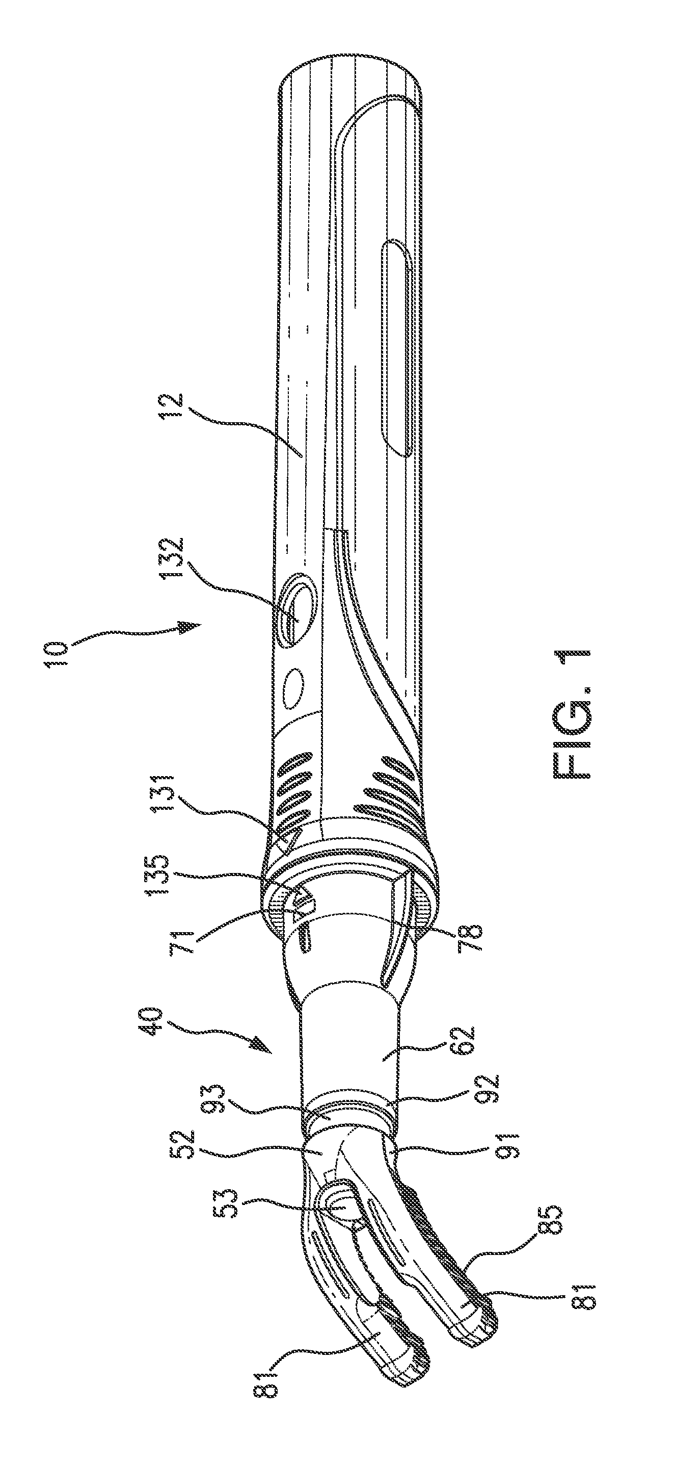
Figure 2 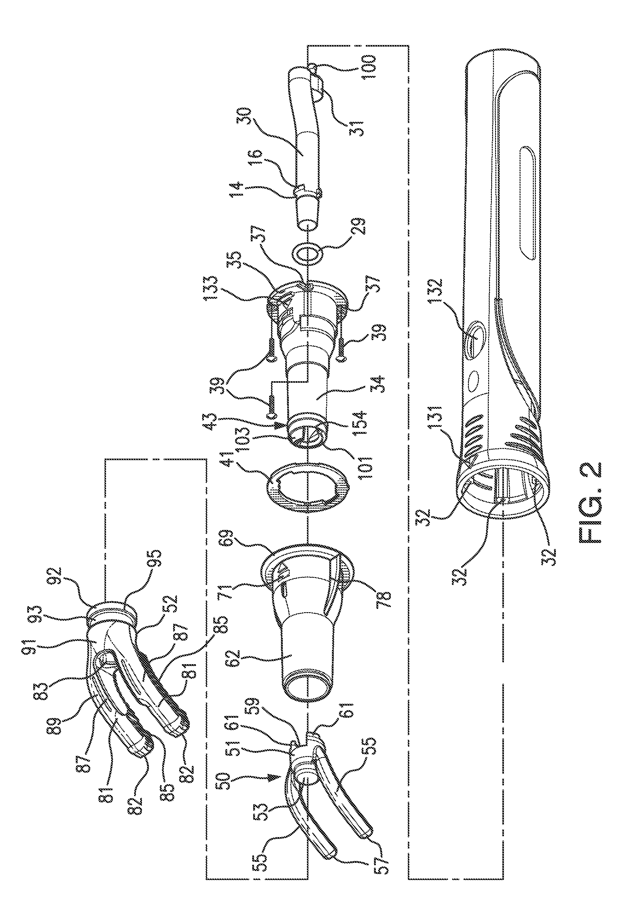
Figure 3
Abstract
Description
CROSS REFERENCE TO RELATED APPLICATIONS
[0001] This application and the invention described herein is a continuation-part of U.S. application Ser. No. 13 / 225,782, filed Sep. 6, 2011, which is a continuation-part of PCT Application No. PCT / US2010 / 028858 filed Mar. 26, 2010, which is a continuation-in-part of PCT Application No. PCT / US09 / 66033 filed Nov. 29, 2009, which is a continuation-part of co-pending U.S. application Ser. No. 11 / 575,564 filed Mar. 19, 2007, all of which applications are here incorporated by reference in their entirety.FIELD OF INVENTION
[0002] The invention relates to improvements to a method, article and apparatus for use in medical and dental procedures, and particularly to improvements to a method and apparatus in the form of a retractor vibrator and the article in the form of a disposable tip for reducing or minimizing pain during tissue or skin puncturing procedures, such as, administration by injection, into the gums, skin or other tissue of a patient, of a li...
Examples
Embodiment Construction
[0027]Referring to FIGS. 1 to 12, an embodiment of the improved retractor vibrator is shown generally in FIG. 1 designated as 10 for performing the functions of the present invention, as will be explained hereinafter. Exploded views are shown in FIGS. 2-5. in particular, retractor vibrator 10 is a handheld apparatus comprising a main body or handle 12 in the shape of a tube having a battery cover and an end closure that is threaded to screw onto the open end of handle 12 in a complementary fit. This is as described in WO / 2010 / 111611, hereby incorporated by reference in its entirety. Further as described in WO / 2010 / 111611 handle 12 is composed of hard plastic and partially receives a chassis, the uncovered portion of which is covered by a battery cover. Rechargeable batteries, not shown in FIG. 1, are located in a battery compartment of the chassis. An induction coil is mounted on the end of chassis and positioned in the battery cover to couple to a charge device in a conventional ma...