
Sensor module that switches plural sensors capable of measuring different ranges to extend dynamic range
Patent Information
- Authority / Receiving Office
- US · United States
- Current Assignee / Owner
- Publication Date
- 2017-04-20
Smart Images
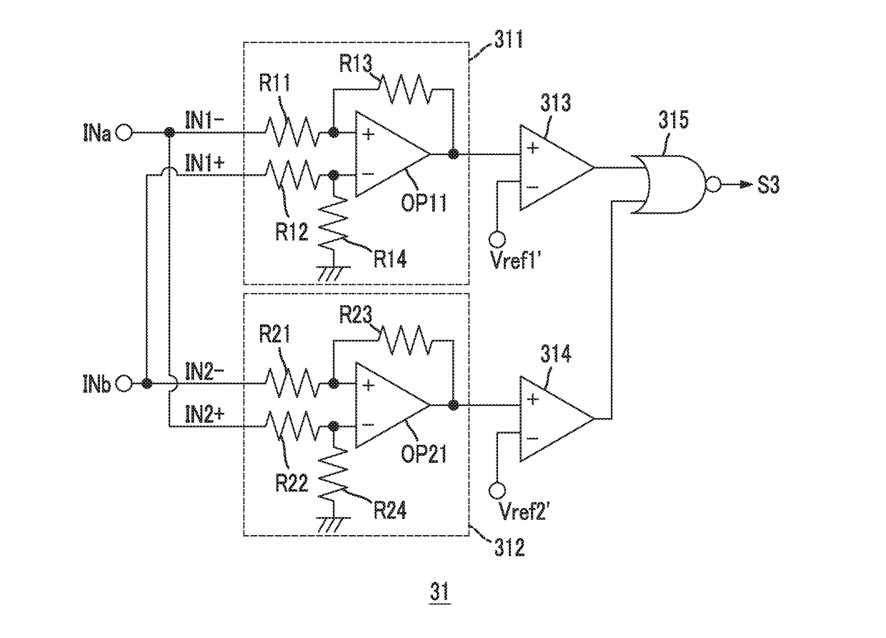
Figure 1 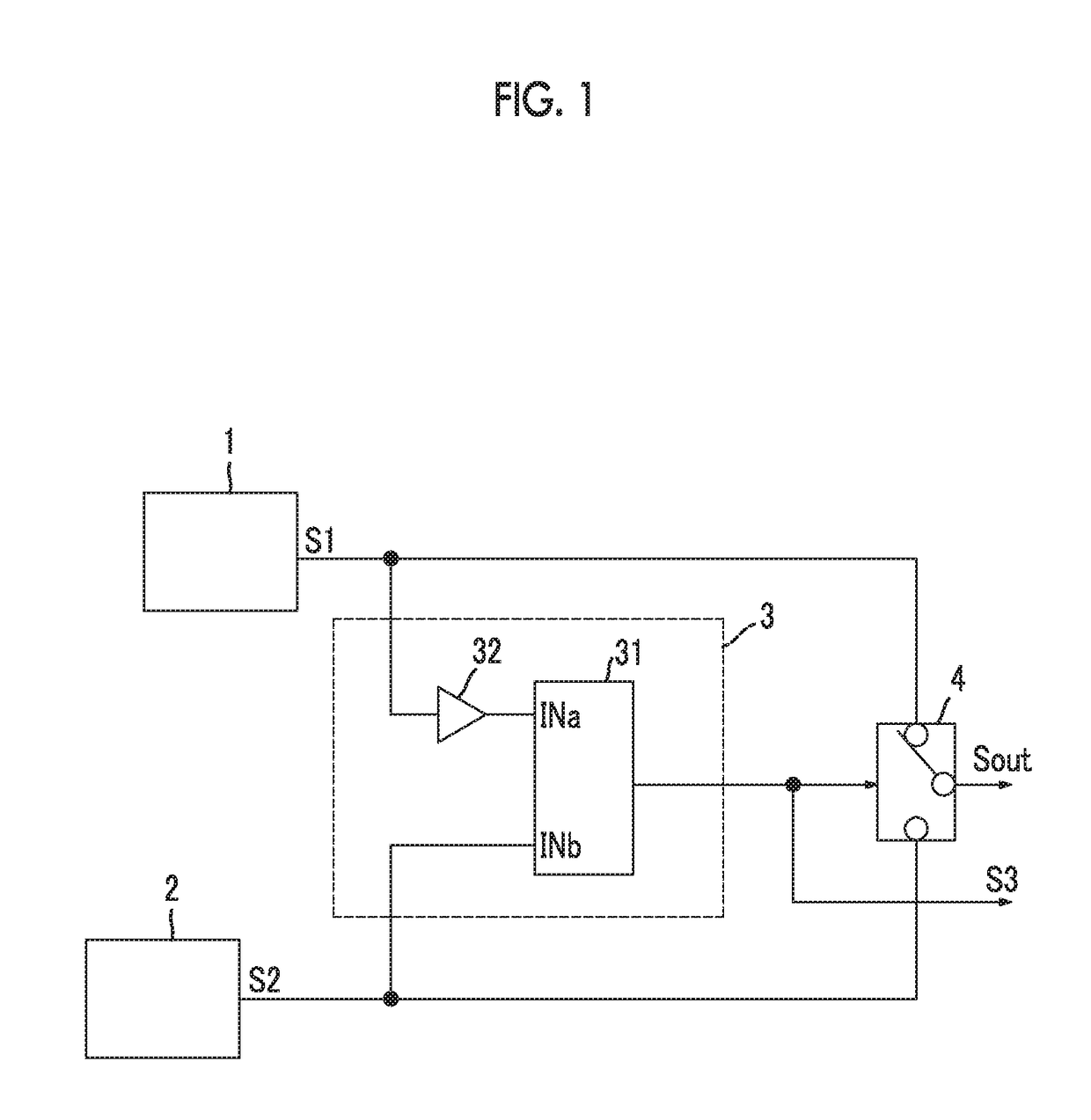
Figure 2 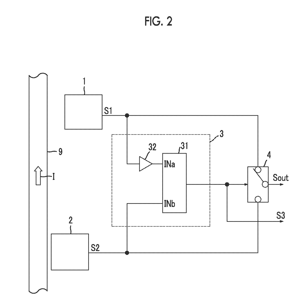
Figure 3
Abstract
Description
CLAIM OF PRIORITY
[0001] This application is a Continuation of International Application No. PCT / JP2015 / 071812 filed Jul. 31, 2015, which claims priority to Japanese Patent Application No. 2014-159849 filed on Aug. 5, 2014, which are hereby incorporated by reference.BACKGROUND OF THE INVENTION
[0002] 1. Field of the Invention
[0003] The present invention relates to a sensor module that switches a plurality of sensors capable of measuring different ranges to extend a dynamic range, and particularly relates to a technique suitable for a current sensor module using a plurality of magnetic sensors capable of measuring different magnitudes of magnetic fields.
[0004] 2. Description of the Related Art
[0005] As a method of extending the range of measurement of a sensor, a method of switching sensors capable of detecting different magnitudes of physical quantities is generally known. In a sensitivity switching-type sensor circuit disclosed in U.S. Pat. No. 7,382,150 B2 described below, the voltages o...
Examples
first embodiment
[0048]FIG. 1 is a diagram illustrating an example of a configuration of a sensor module according to a first embodiment of the present invention. This sensor module is a sensor module that measures a physical quantity through sensors (1 and 2), and switches between and uses two sensors (1 and 2) different from each other in sensitivity to a physical quantity in accordance with the range of measurement. Examples of physical quantities to be measured include magnetism, current, voltage, power, electrical resistance, temperature, acceleration, velocity, illuminance, volume level, pressure, humidity, malodor, the sense of taste, vibration, length, liquid level, and flow rate. Particularly, the details of a current sensor module using a magnetic sensor will be described later. In FIG. 1, configurations and operations which are applicable to even cases where any physical quantities are measured will be described.
[0049]The current sensor module shown in FIG. 1 includes a first sensor 1 and...
second embodiment
[0122]Next, a second embodiment of the present invention will be described.
[0123]FIG. 5 is a diagram illustrating an example of a configuration of a current sensor module according to the second embodiment. The current sensor module shown in FIG. 5 has the same configuration as that of the current sensor module shown in FIG. 2, and includes a first low-pass filter 11 and a second low-pass filter 12.
[0124]The first low-pass filter 11 attenuates a high frequency component such as noise included in the output of the first magnetic sensor 1. The output of the first magnetic sensor 1 passes through the first low-pass filter 11 and is input to the selection unit 4 and the comparison unit 3.
[0125]The second low-pass filter 12 attenuates a high frequency component such as noise included in the output of the second magnetic sensor 2. The output of the second magnetic sensor 2 passes through the second low-pass filter 12 and is input to the selection unit 4 and the comparison unit 3.
[0126]Eac...
third embodiment
[0129]Next, a third embodiment of the present invention will be described.
[0130]FIG. 5 is a diagram illustrating an example of a configuration of a current sensor module according to the third embodiment. The current sensor module shown in FIG. 6 has the same configuration as that of the current sensor module shown in FIG. 2, and includes a first low-pass filter 11, the second low-pass filter 12, and an off-delay timer 5.
[0131]The first low-pass filter 11 and the second low-pass filter 12 are the same as the components denoted by the same reference numerals in the current sensor module shown in FIG. 5. However, the above current sensor module is different from the current sensor module shown in FIG. 5, in that the outputs of the first magnetic sensor 1 and the second magnetic sensor 2 are input to the comparison unit 3 without passing through these low-pass filters (11 and 12). That is, the comparison unit 3 compares the current level (first current level) of the current I to be mea...