
Pneumatic multi-valve device and production method
Patent Information
- Authority / Receiving Office
- US · United States
- Current Assignee / Owner
- Publication Date
- 2019-04-25
Smart Images
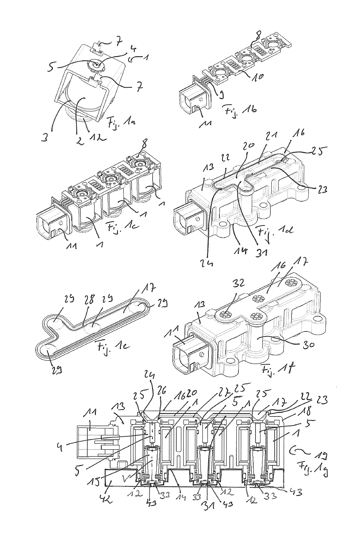
Figure 1 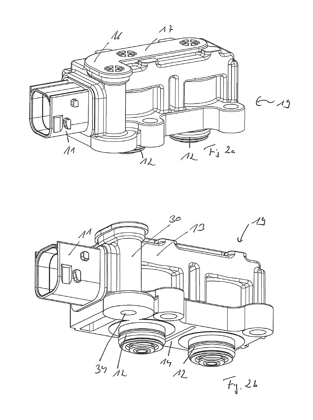
Figure 2 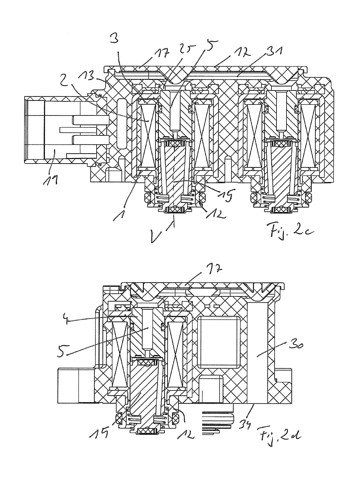
Figure 3
Abstract
Description
BACKGROUND OF THE INVENTION
[0001] The invention relates to a pneumatic multi-valve device (valve block), in particular for use in electronically regulated air spring systems of vehicles, preferably utility vehicles, comprising a housing, which has a housing main body with a plurality of electromagnetic valve actuators, each having coil elements arranged in the housing in a stationary manner, a core arranged in the housing, and armature elements, which can be displaced along a displacement axis in the housing in relation to the core and in relation to a (respective) pneumatic connection of the housing in response to energization of the coil elements, wherein the displacement axes of the (plurality of) armature elements of the valve actuators are oriented parallel and the pneumatic connections associated with the armature elements are arranged adjacent to each other on a connection housing side, which is spaced apart from a housing back side facing away therefrom along the displacement...
Examples
Embodiment Construction
[0030]FIGS. 1a to 1e show different assembly steps and components for producing a valve device according to the invention, which is illustrated in FIG. 1f in a perspective view and which, in turn, is illustrated in a sectional view in FIG. 1g.
[0031]FIG. 1a shows a preassembled, electromagnetic valve actuator 1, of which a plurality—here for example three pieces—is provided in the finished multi-valve device (valve block) illustrated in FIGS. 1f and 1g. The electromagnetic valve actuator 1 comprises an energizable coil element 2 (electrical winding), which is arranged on a coil carrier 3, which is embodied as plastic injection molded part. A core 4 for the electromagnetic interaction with non-illustrated armature elements is located in a central passage opening (central bore) of the coil carrier 3. A central venting bore 5 is provided in the core 4. The coil elements 3 are clasped by a magnetically conducting yoke 6 for surrounding the magnetic circuit. Electrical contact elements 7...