
Hydrodynamic clutch device
Patent Information
- Authority / Receiving Office
- US · United States
- Current Assignee / Owner
- Publication Date
- 2008-10-02
Smart Images
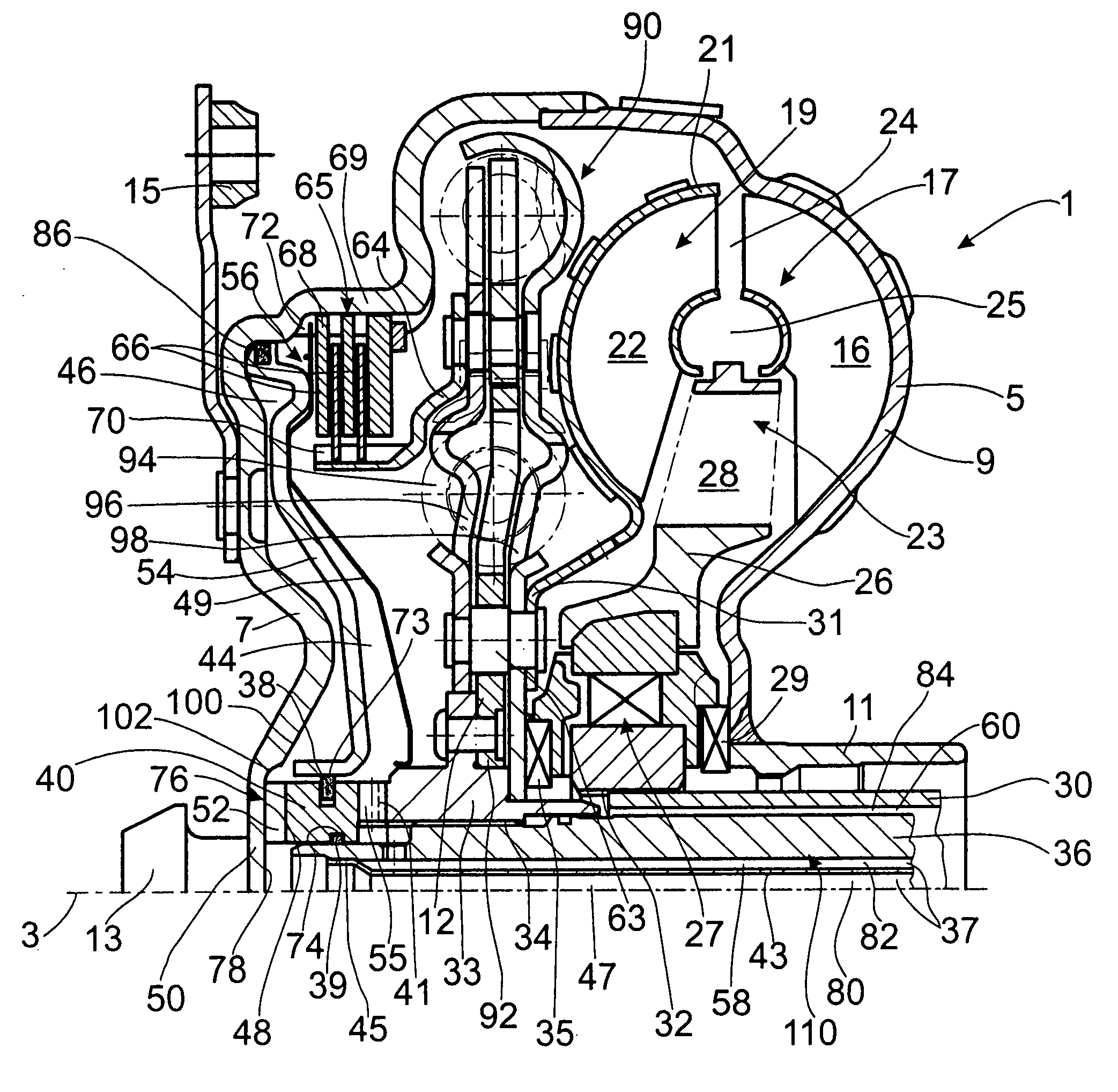
Figure 1 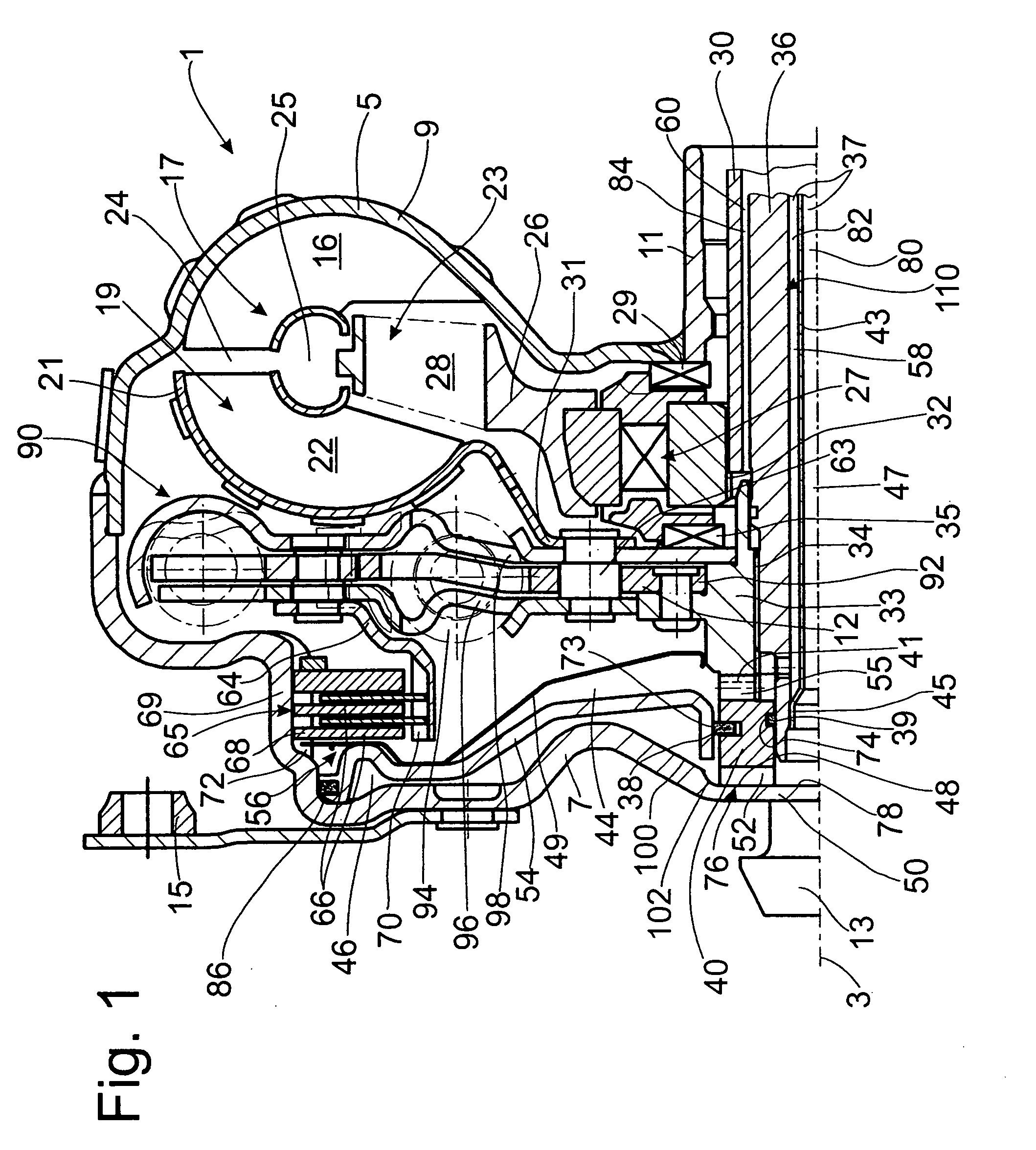
Figure 2 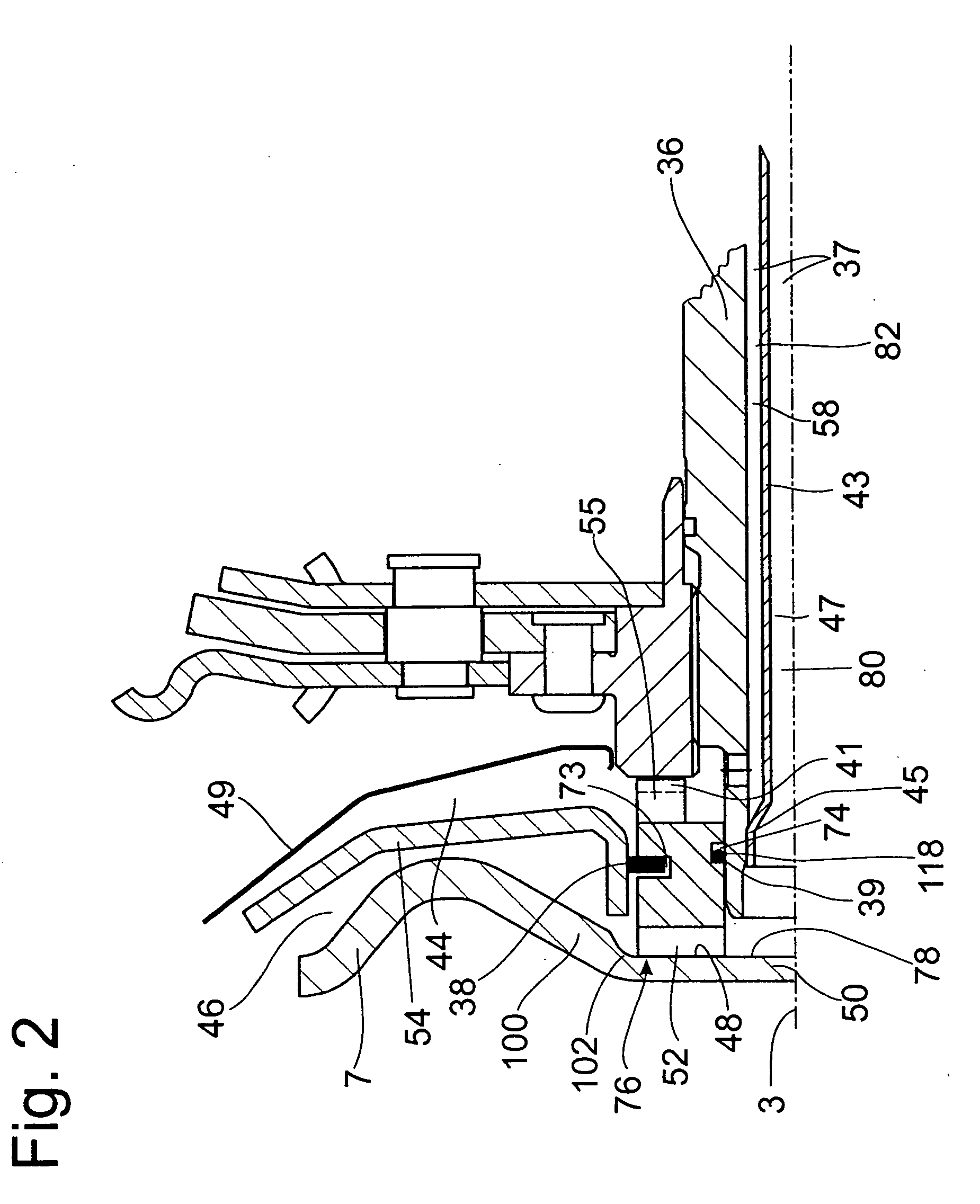
Figure 3
Abstract
Description
BACKGROUND OF THE INVENTION
[0001] 1. Field of the Invention
[0002] The invention pertains to a hydrodynamic clutch device of the type including a clutch housing which is rotatable about an axis of rotation and has a drive-side housing wall, a hydrodynamic circuit including a pump wheel and a turbine wheel in the clutch housing, and a bridging clutch having a piston capable of shifting axially relative to the drive-side housing wall, the piston separating a pressure space adjacent to the drive-side housing wall from a supply space.
[0003] 2. Description of the Related Art
[0004] A hydrodynamic clutch device designed as a hydrodynamic torque converter is known from U.S. Pat. No. 5,964,320. A pump wheel cooperates with a turbine wheel and a stator to form a hydrodynamic circuit in a clutch housing; this circuit cooperates with a bridging clutch. The bridging clutch has a piston, which can be connected to a drive-side housing wall of the clutch housing and shifted in the axial direction. This ...
Examples
Embodiment Construction
[0027]FIG. 1 shows a hydrodynamic clutch device 1, designed as a hydrodynamic torque converter. The hydrodynamic clutch device 1 has a clutch housing 5, which is able to rotate around an axis of rotation 3. On the side facing a drive (not shown), such as the crankshaft of an internal combustion engine, the clutch housing 5 has a drive-side housing wall 7, which is permanently connected to a pump wheel shell 9. This merges in the radially inner area with a pump wheel hub 11.
[0028]To return to the drive-side housing wall 7: On the side facing the drive (not shown), this wall has a bearing journal 13, which, in a manner which is already known and therefore not illustrated in detail, is supported on an element of the drive, such as the crankshaft, for the drive-side mounting of the clutch housing 5. In addition, the drive-side housing wall 7 has fastening mounts 15, which serve in the conventional manner to allow the clutch housing 5 to be fastened to the drive, preferably by way of a f...