
Adjustable sizing tube
Patent Information
- Authority / Receiving Office
- US · United States
- Current Assignee / Owner
- Publication Date
- 2005-09-20
Smart Images
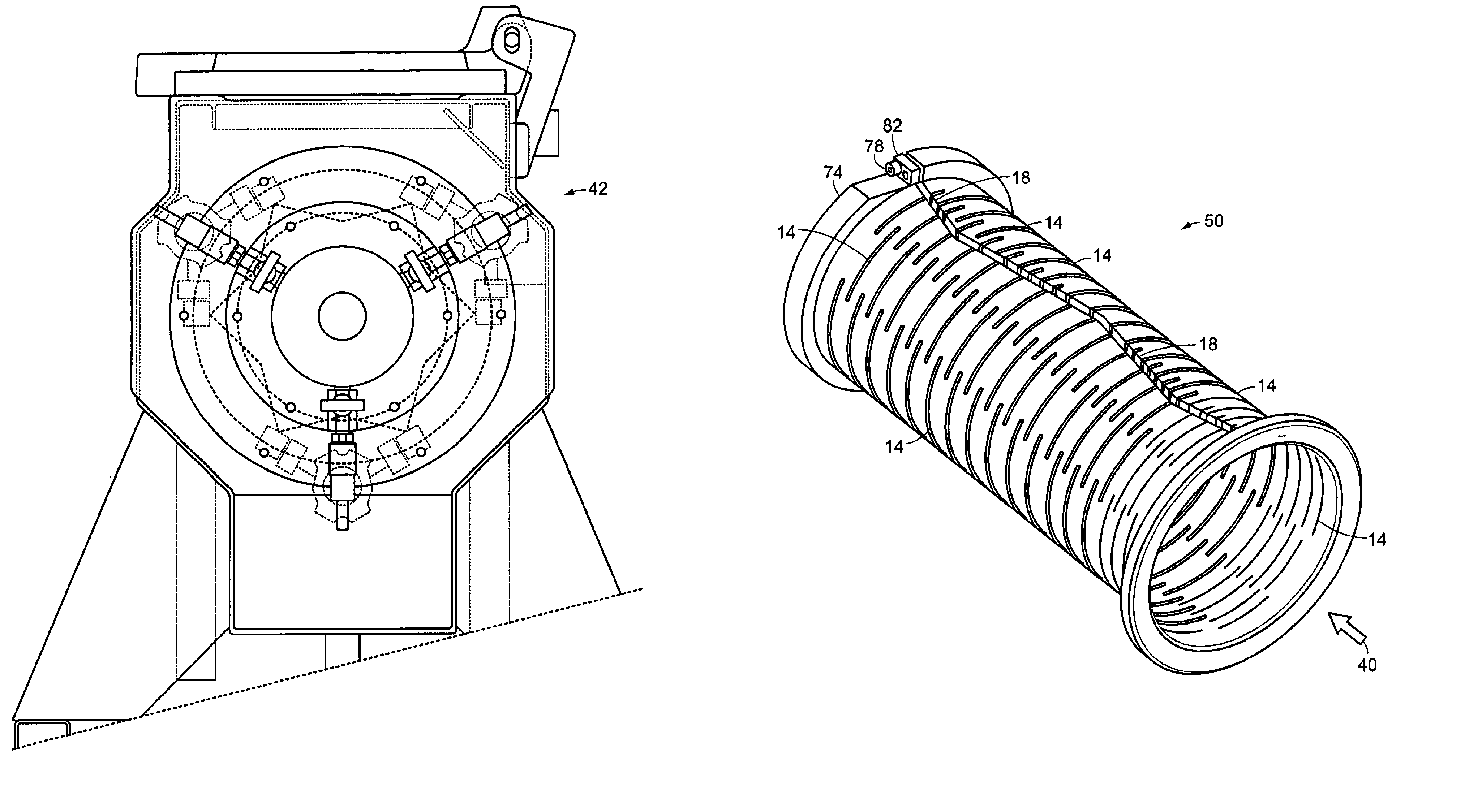
Figure 1 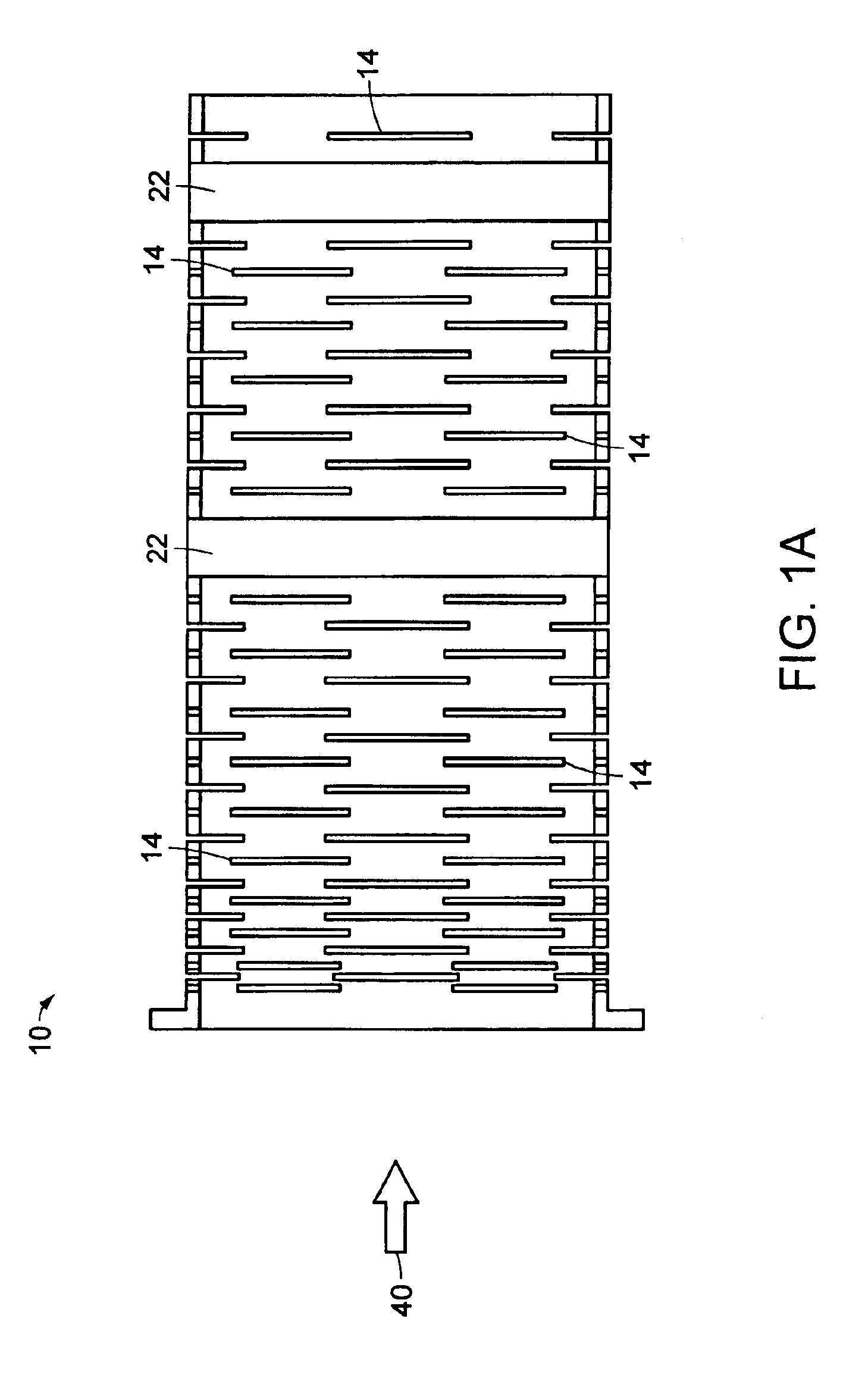
Figure 2 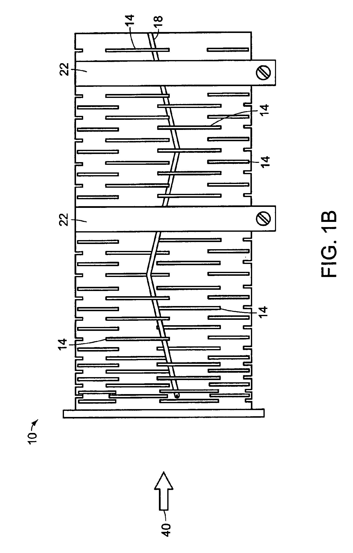
Figure 3
Abstract
Description
BACKGROUND OF THE INVENTION
[0001] When extruding polyvinyl chloride (PVC) pipe, an adjustable sizing tube is used to guide, create and maintain the final outside dimensional configuration of the extruded pipe material before the pipe material has completely hardened. The sizing tube is located within a vacuum-calibration tank (VCT) which is located downstream from an extruder and respective extrusion die. The sizing tube can be either fixed or adjustable. However, the fixed sizing tube is made from a rigid-walled tube and cannot be adjusted. Both types of sizing tubes are characterized by circumferential slotted channel configurations.
[0002] As shown in FIGS. 1A and 1B, a prior art adjustable sizing tube 10 has various slotted channel 14 configurations cut circumferentially throughout the length of the sizing tube 10. The slotted channels 14 allow a negative vacuum created in the VCT's chamber to “pull” the extruded pipe material against the inner wall of the sizing tube 10 to maintai...
Examples
Embodiment Construction
[0020]In an extrusion system 26 as shown in FIGS. 2-3B, an extrusion such as extruded PVC pipe is formed by feeding plastic pellets into an extruder 30 where it is subjected to high temperatures to create a molten substrate. The substrate or melt proceeds through an extrusion head, at the end of which the melt passes through an extrusion die 34. The die 34 contains the circular cross-sectional profile shape to be extruded. The extruded pipe 38 exits the die 34 and flows in direction 40 into a vacuum calibration tank (VCT) 42. The VCT 42 cools the walls of the extruded pipe 38 to maintain a fixed shape while it passes through VCT 42. An adjustable sizing tube 50 is located within the VCT 42 to maintain the outer diameter of the extruded pipe 38. The VCT 42 draws a negative vacuum which maintains the walls of the extruded pipe 38 against the inside diameter of the sizing tube 50. The extruded pipe 38 proceeds from the VCT 42 to a spray tank 54 for further cooling of the extruded pipe ...