
Brake fluid reservoir with improved venting
a technology of brake fluid and reservoir, applied in the field of hydraulic brake systems, can solve problems such as difficulty in escaping brake fluid, and achieve the effect of convenient manufacturing
Patent Information
- Authority / Receiving Office
- US · United States
- Patent Type
- Patents(United States)
- Current Assignee / Owner
- Publication Date
- 2007-03-20
- Estimated Expiration
- Not applicable · inactive patent
Smart Images
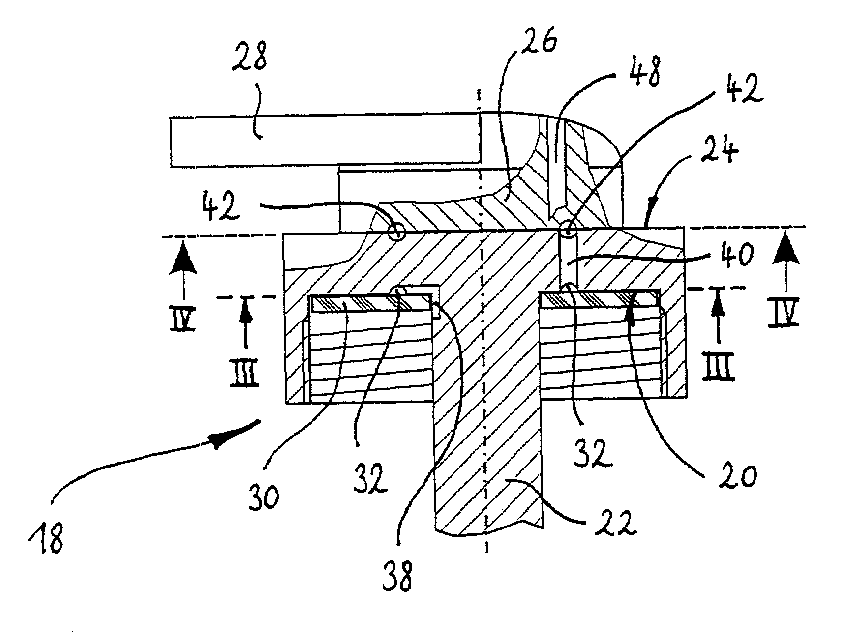
Figure 1 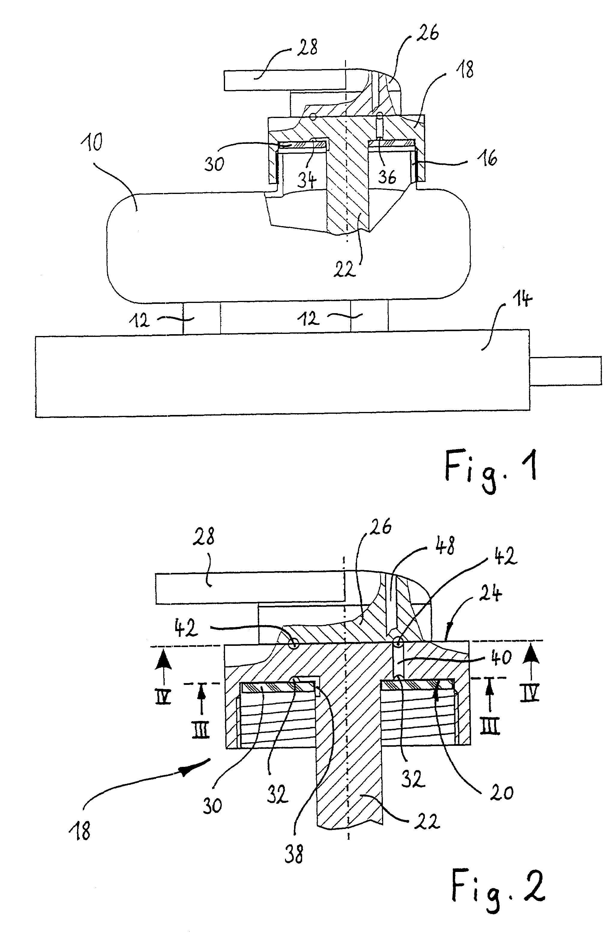
Figure 2 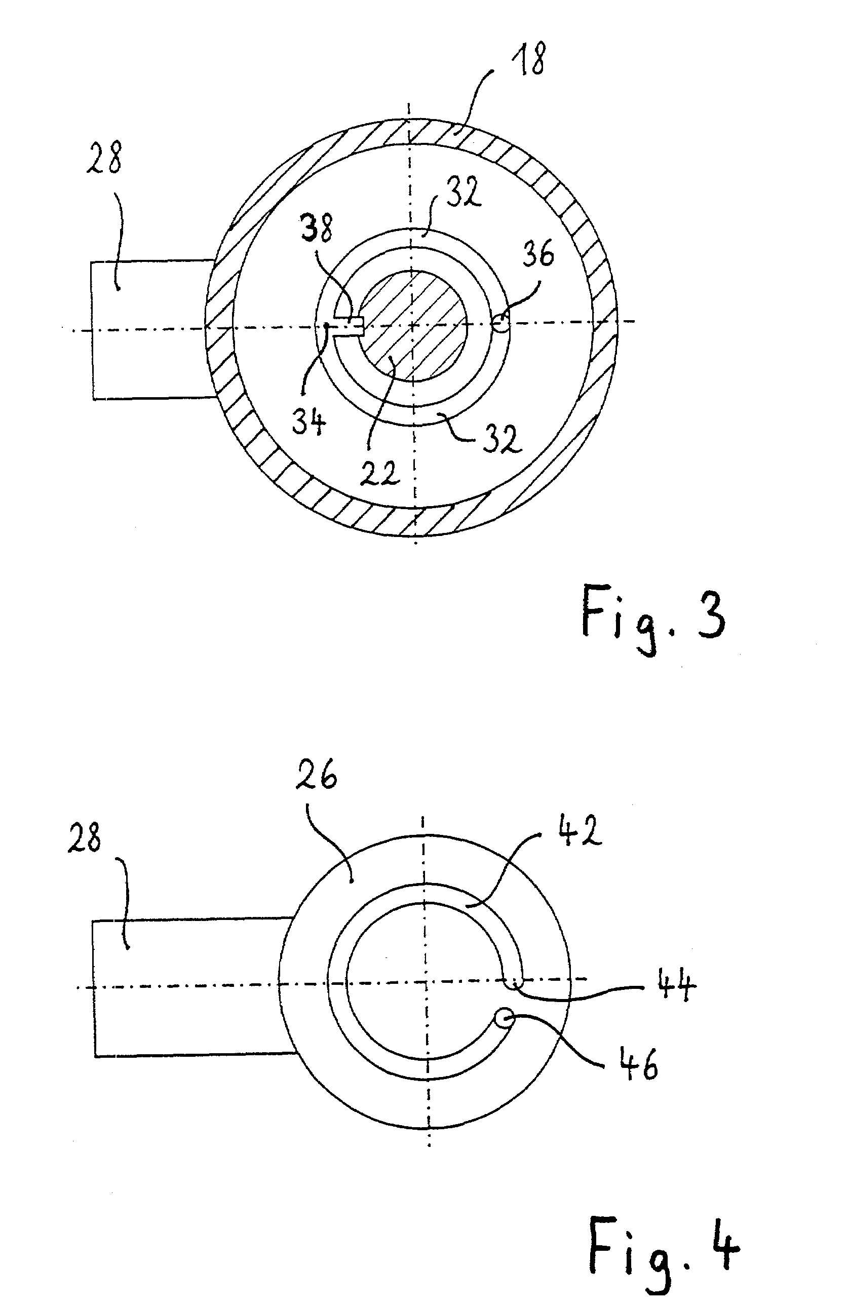
Figure 3
Abstract
Description
CROSS REFERENCE TO RELATED APPLICATIONS
[0001] This application is a continuation of International Application No. PCT / EP00 / 09815 filed Oct. 6, 2000, which claims priority to German Patent Application No. 19952336.3 filed Oct. 29, 1999, the disclosures of which are incorporated herein by reference.
[0002] The invention relates to a brake fluid reservoir for a vehicle hydraulic brake system. Such a brake fluid reservoir is known from DE 31 22 085 A1.BACKGROUND OF THE INVENTION
[0003] Vehicle hydraulic brake systems comprise a brake fluid reservoir, which is usually seated on the master cylinder of the vehicle brake system and connected by means of two couplings in a fluid-conducting manner to the master cylinder. Hydraulic fluid, which is needed to balance the fluid content of the brake system, flows from said brake fluid reservoir into the brake system. Surplus brake fluid moreover flows from the brake system into the brake fluid reservoir. The brake fluid reservoir is accordingly used t...
Examples
Embodiment Construction
[0022]FIG. 1 shows a brake fluid reservoir 10 of a vehicle hydraulic brake system, which reservoir is connected in a fluid-conducting manner by two couplings 12 extending from its underside to an only diagrammatically reproduced master cylinder 14. As millions of such brake fluid reservoirs are in use, their function is known to experts in the present field and requires no further explanation here.
[0023]The reservoir 10 is made of transparent plastics material and has, formed on its top side, a filler neck 16 having an external thread. Screwed onto the filler neck 16 is a substantially round lid 18, which is provided with an internal thread and closes the opening of the filler neck 16.
[0024]The lid 18, which is shown in greater detail in FIGS. 2 to 4, is made of plastics material and has an underside 20, from which a rod-shaped extension 22 extends into the reservoir interior. Extending through the extension 22 is a sensor device, which is not illustrated here and which detects the ...