
Low profile load beam with etched cavity for PZT microactuator
a microactuator and load beam technology, applied in the field of low-profile suspensions, to achieve the effect of improving the inertial balancing of the suspension, avoiding windage, and avoiding bending
Patent Information
- Authority / Receiving Office
- US · United States
- Current Assignee / Owner
- Publication Date
- 2012-04-03
Smart Images
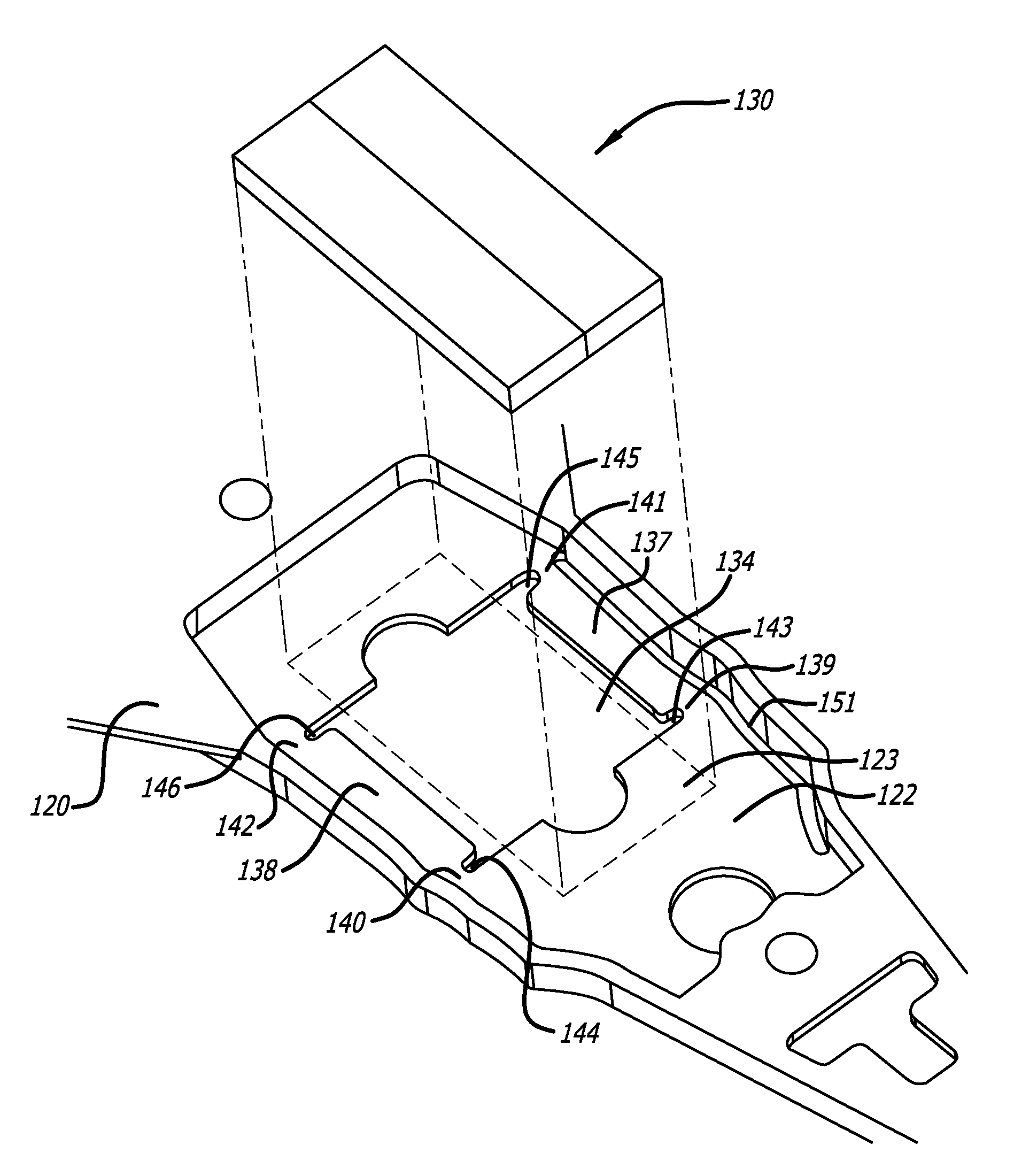
Figure 1 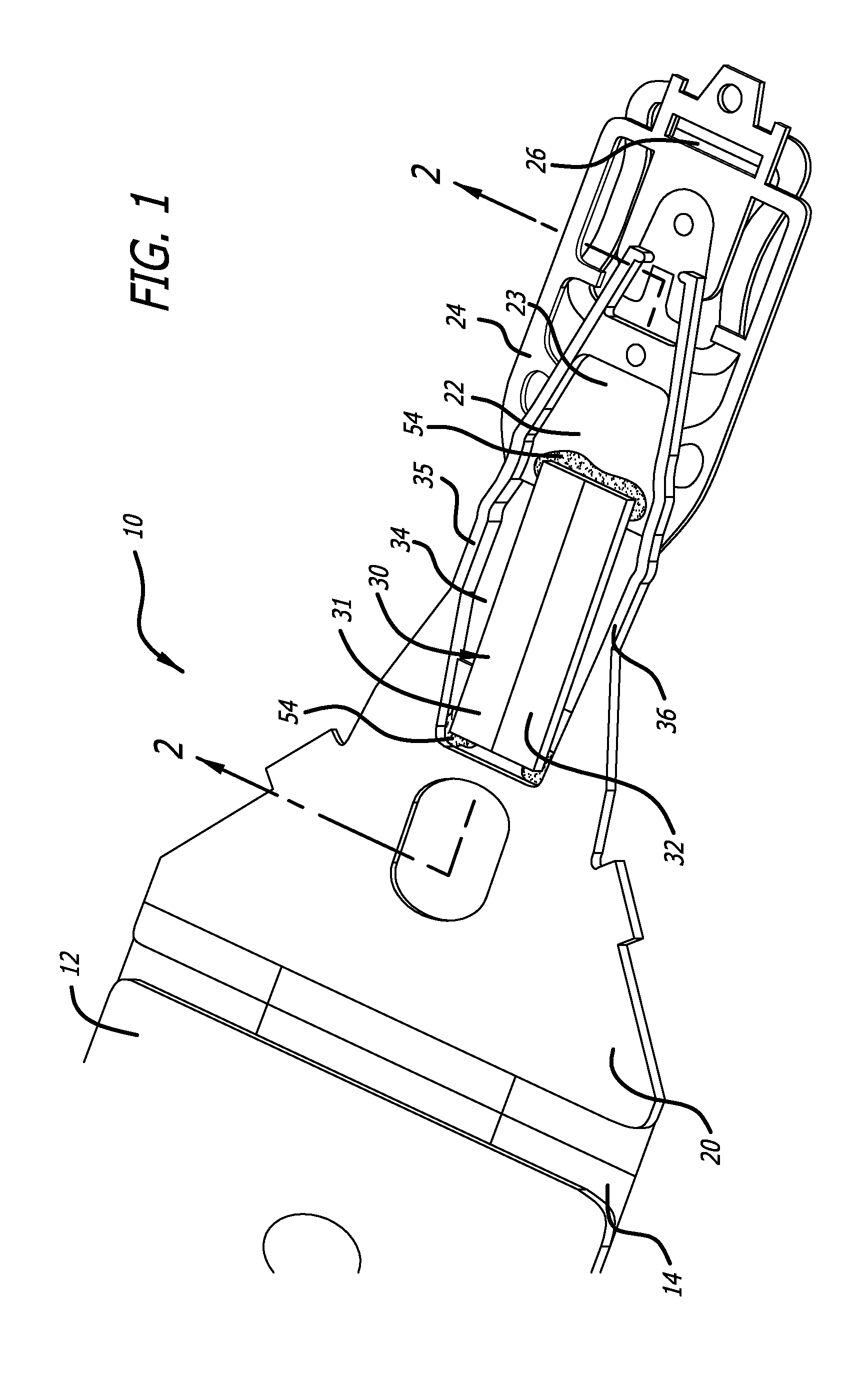
Figure 2 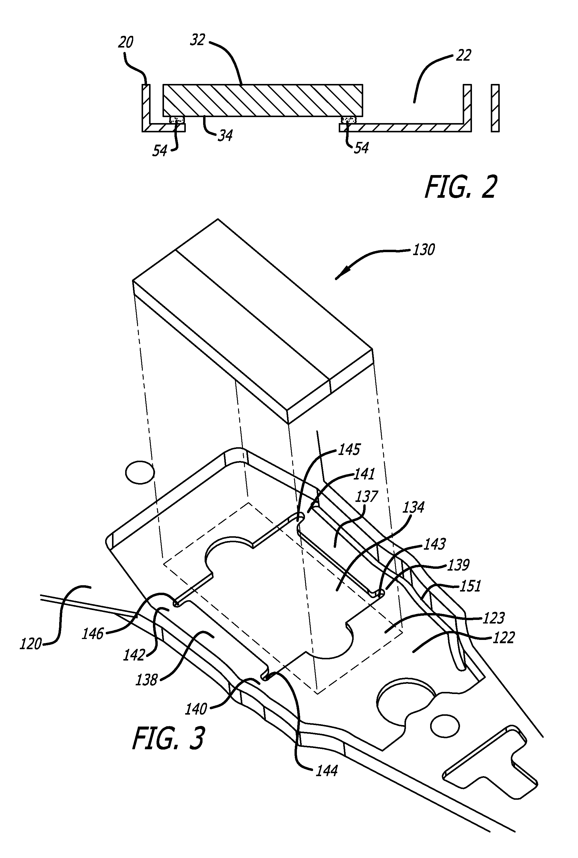
Figure 3
Abstract
Description
CROSS-REFERENCE TO RELATED APPLICATIONS
[0001] This application claims priority from U.S. Provisional Application No. 61 / 107,926 filed Oct. 23, 2008.BACKGROUND OF THE INVENTION
[0002] 1. Field of the Invention
[0003] This invention relates to the field of disk drive suspensions. More particularly, this invention relates to the field of a low profile suspension having a cavity formed therein for receiving a microactuator.
[0004] 2. Description of Related Art
[0005] The suspension is the component of a magnetic hard disk drive, or other type of disk drive such as an optical disk drive, that holds the read / write head over the surface of the spinning disk. A servo-controlled voice coil motor (VCM) moves the suspension and thus positions the read / write head precisely over the desired data track on the disk.
[0006] Due to the increasing data densities in modern disk drives, in addition to the VCM for coarse positioning of the read / write head, many suspensions now also incorporate a microactuator on t...
Examples
first embodiment
[0025]FIG. 1 shows a first embodiment according to a first major aspect of this invention. The electrical leads and electrical interconnect have been omitted for clarity of illustration. Suspension 10 includes a base portion such as a base plate 12 at a proximal end of the suspension, hinges or springs 14, load beam 20, and flexure 24 including a head gimbal on which slider 26, which contains the read / write head, is mounted. Slider 26 is mounted at or near a distal end of load beam 20. According to this embodiment, a recess or recessed cavity 22 is etched into load beam 20 via partial etching of the load beam, by laser ablation, or by other suitable forming method, and is located distal of load beam spring hinges 14. In the exemplary embodiment, a split PZT 30, which has a left side PZT element 31 and a right side PZT element 32, is fitted into cavity 22 to span aperture 34 in cavity floor 23, and is electrically connected to the microactuator driving voltage. Thus, the foot print o...
second embodiment
[0032]FIG. 3 is an oblique exploded view of the dimple side opposite the slider side of a load beam having a cavity into which a PZT is mounted according to the invention, and FIG. 4 is oblique view of the slider side of the load beam of FIG. 3. Load beam 120 has cavity 122 formed therein, including cavity floor 123 and aperture 134. Microactuator motor 130 is positioned within aperture 134 to extend across aperture 134. In this embodiment trenches 151 and 152 are formed adjacent to side rails 135 and 136, respectively, and extend generally longitudinally at least partially laterally adjacent to microactuator 130 and aperture 134. Trenches 151 and 152, which constitute elongated apertures extending generally longitudinally through cavity floor 123, render load beam 120 more flexible in the area of side rails 135 and 136. In the embodiment shown trenches 151 and 152 extend generally longitudinally adjacent to and along the side rails 135 and 136, and separate side rails 135 and 136 f...
third embodiment
[0037]FIG. 5 is an oblique view of the dimple side of a load beam having a cavity for a PZT according to the invention. FIG. 6 is an oblique view of the slider side of the load beam of FIG. 5. In this embodiment there are no sway stiffeners. Rather, aperture 234 extends laterally all the way to side rails 235 and 236. As in the embodiment of FIG. 3, trenches 251 and 252 extend generally longitudinally along side rails 235 and 236, and extend distally beyond the distal most extent of the PZT (not shown) that will be placed into cavity 234 and adhered therein.
[0038]In one possible embodiment (not illustrated) the load beam cavity could be very slightly longer than the PZT to allow the PZT to be fitted into the cavity closely enough so that as the PZT expands, it presses directly against the proximal and distal walls of the cavity thereby causing the distal end of the load beam to move.
[0039]In another possible embodiment (also not illustrated), there could be a small gap between the p...