
Air-intake duct and air-intake structure
a technology of air-intake duct and air-intake structure, which is applied in the direction of machine/engine, combustion-air/fuel-air treatment, charge feed system, etc., can solve the problems of degrading the air-guiding function, increasing the weight of the air-intake duct, and difficulty in performing the functions in a well-balanced manner. , to achieve the effect of reducing weight, improving fuel efficiency and well-balanced manner
Patent Information
- Authority / Receiving Office
- US · United States
- Patent Type
- Patents(United States)
- Current Assignee / Owner
- Publication Date
- 2013-09-03
Smart Images
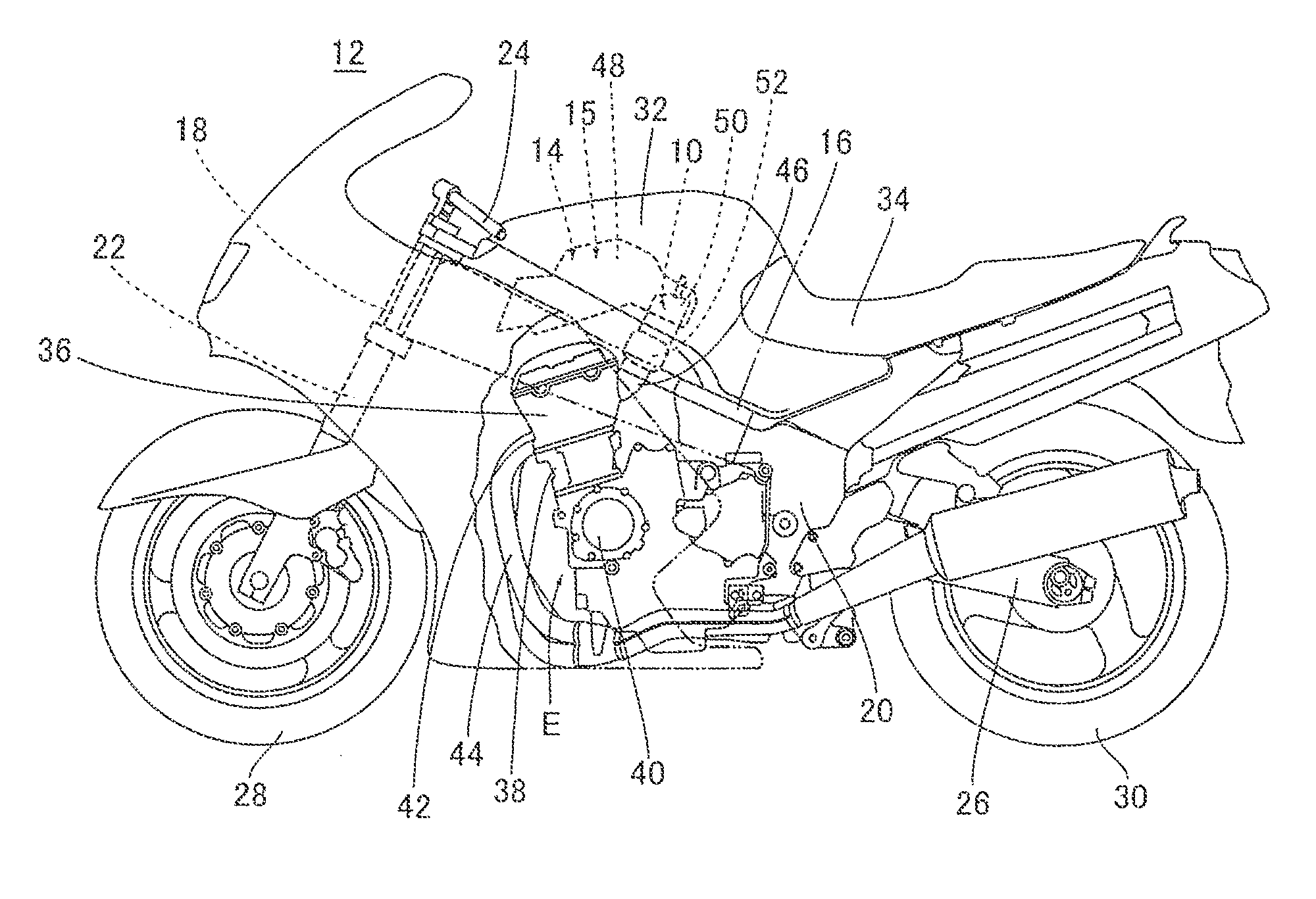
Figure 1 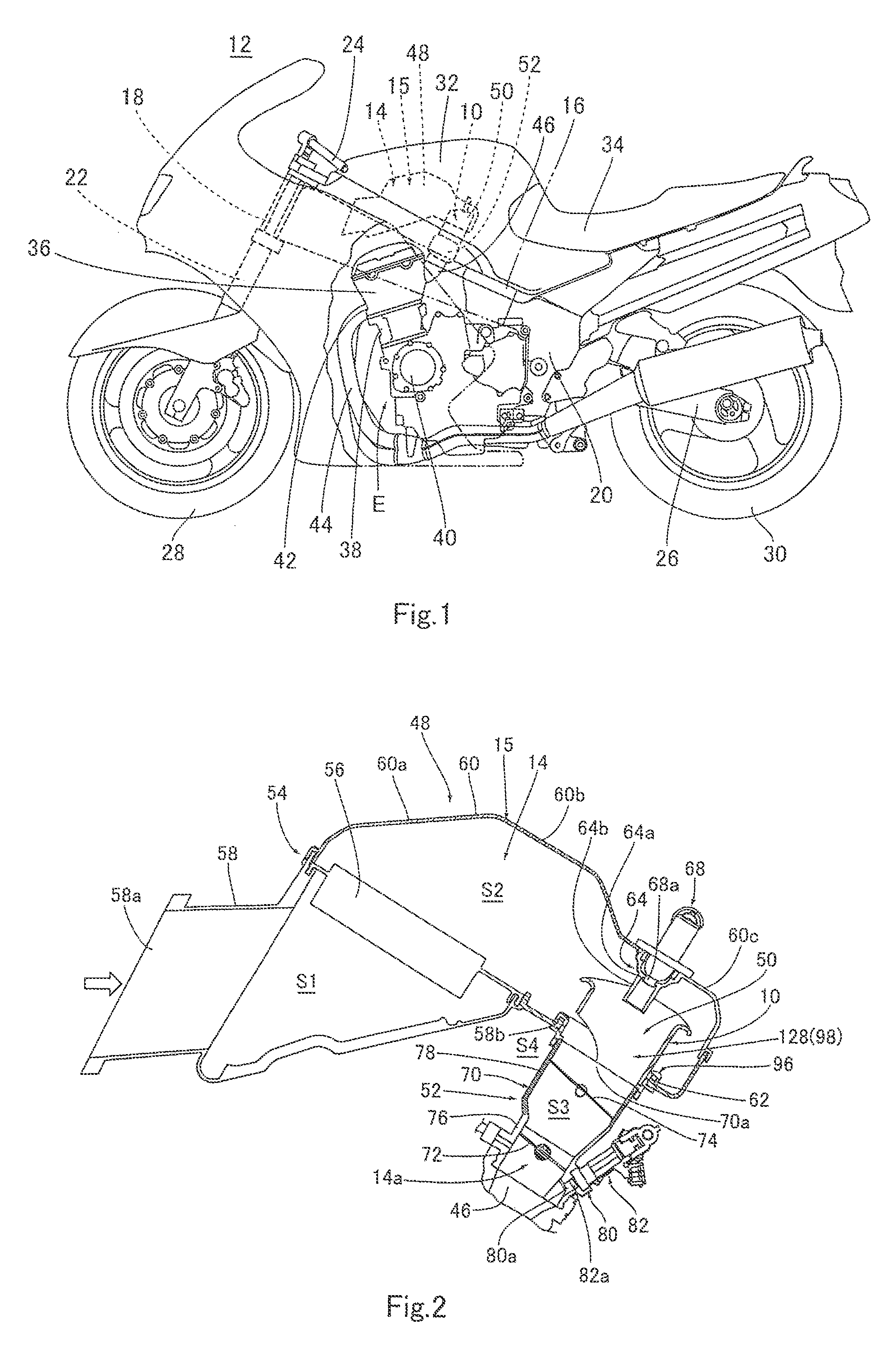
Figure 2 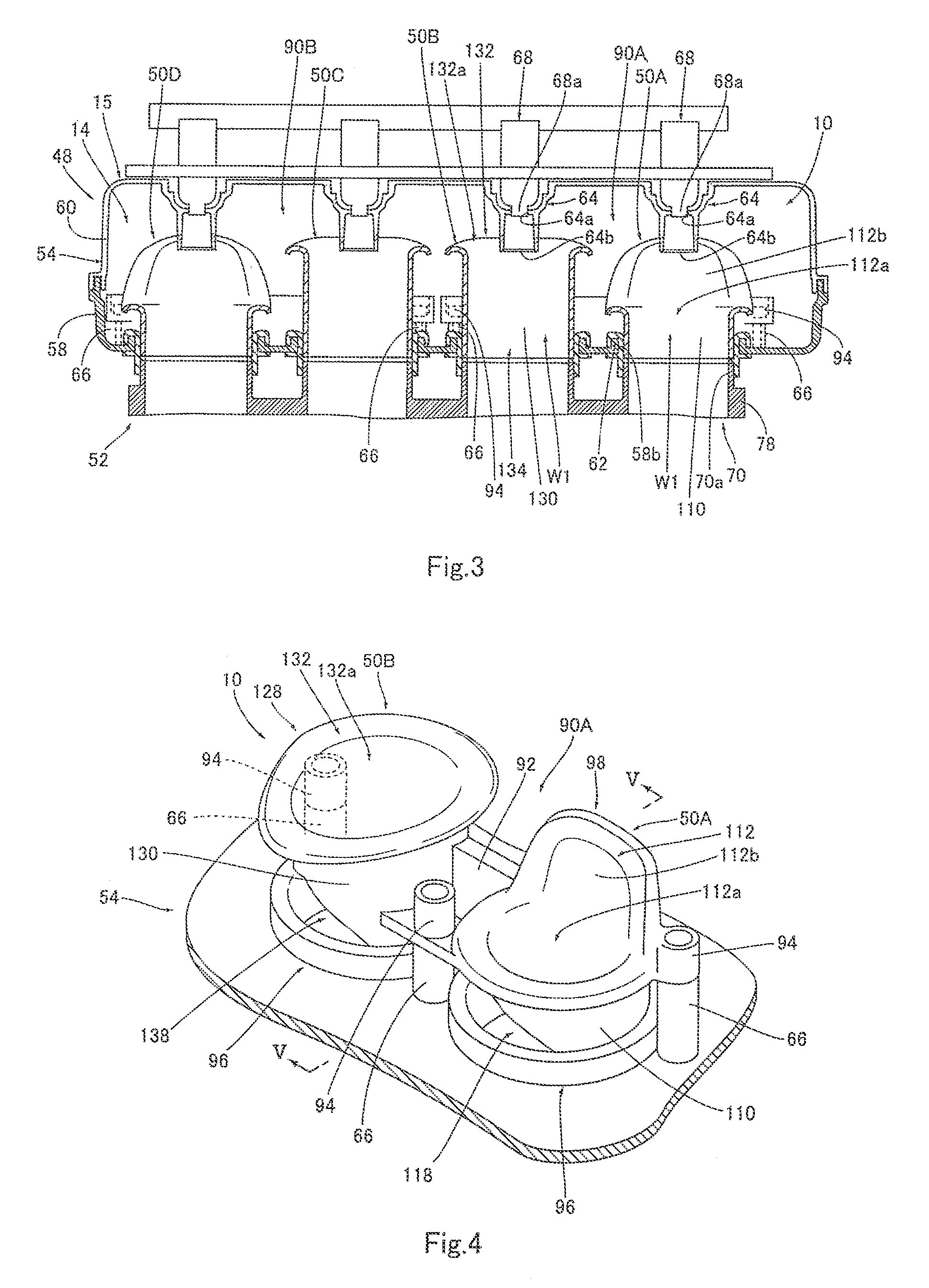
Figure 3
Abstract
Description
CROSS-REFERENCE TO RELATED APPLICATION
[0001] The present application claims priority to Japanese Patent Application No. 2009-29919 filed on Dec. 29, 2009, which is hereby incorporated by reference in its entirety for all purposes.BACKGROUND ART
[0002] 1. Field of the Invention
[0003] The present invention relates to an air-intake duct and an air-intake structure for guiding air to a throttle device coupled to an engine.
[0004] 2. Description of the Related Art
[0005] An engine mounted in a motorcycle and other vehicles includes a cylinder head having a combustion chamber. An air-intake structure forming an air-intake passage is coupled to an intake port of the combustion chamber to guide air and fuel to the combustion chamber. The air-intake structure typically includes an air cleaner box of an air cleaner, an air-intake duct, and a throttle body of a throttle device which are coupled to each other in this order from an upstream side in an air flow direction. The throttle body is provided wi...
Examples
embodiment 1
[Construction of Motorcycle]
[0047]FIG. 1 is a left side view of a construction of an entire motorcycle 12 including an air-intake structure 15 including an air-intake duct structure 10 according to Embodiment 1. FIG. 2 is a cross-sectional view showing a configuration of the air-intake structure 15.
[0048]Referring now to FIG. 1, the motorcycle 12 includes a main frame member 16, a head pipe 18 provided at the front portion of the main frame member 16 and a pair of right and left pivot frame members 20 provided at the rear portion of the main frame member 16. A steering shaft (not shown) is rotatably inserted into the head pipe 18. A front fork 22 and a steering handle 24 are attached to the steering shaft. A pair of right and left swing arms 26 are attached to the pivot frame members 20, respectively. A front wheel 28 is mounted to the lower end portion of the front fork 22. A rear wheel 30 is mounted to the rear end portions of the swing arms 26. A fuel tank 32 and a seat 34 are ar...
embodiment 2
(Embodiment 2)
[0086]FIG. 7 is an exploded perspective view showing a part of an air-intake duct structure 160 including air-intake ducts 50 according to Embodiment 2. Although in the air-intake duct structure 10 according to Embodiment 1, the two air guide members 98 and 128 are coupled to each other to form one air guide unit 150, the four air guide members 98 and 128 may be coupled to each other or may be formed independently of each other.
[0087]In the air-intake duct structure 160 of Embodiment 2, the four air guide members 98 and 128 are formed independently of each other and one fastening portion 94 is provided for each of the four air guide members 98 and 128.
embodiment 3
(Embodiment 3)
[0088]FIG. 8 is a cross-sectional view showing a part of an air-intake duct structure 170 including air-intake ducts 50 according to Embodiment 3. Although in the air-intake duct structure 10 of Embodiment 1, all of the four air guide members 98 and 128 are fastened to the lower case 58, a part or all of them may be fastened to the upper case 60.
[0089]In the air-intake duct structure 170 of Embodiment 3, all of the four air guide members 98 and 128 are fastened to the upper case 60, and the fastening portions 66 are formed inside the upper case 60.