
Crossbar circuitry for applying an adaptive priority scheme and method of operation of such crossbar circuitry
a crossbar circuit and priority scheme technology, applied in the field of crossbar circuitry, can solve the problems of large consumption of power, large complexity of crossbar circuits, and many known techniques that are impractical, and achieve the effect of simple, scalable and power-efficient mechanisms
Patent Information
- Authority / Receiving Office
- US · United States
- Patent Type
- Patents(United States)
- Current Assignee / Owner
- Publication Date
- 2013-10-01
Smart Images
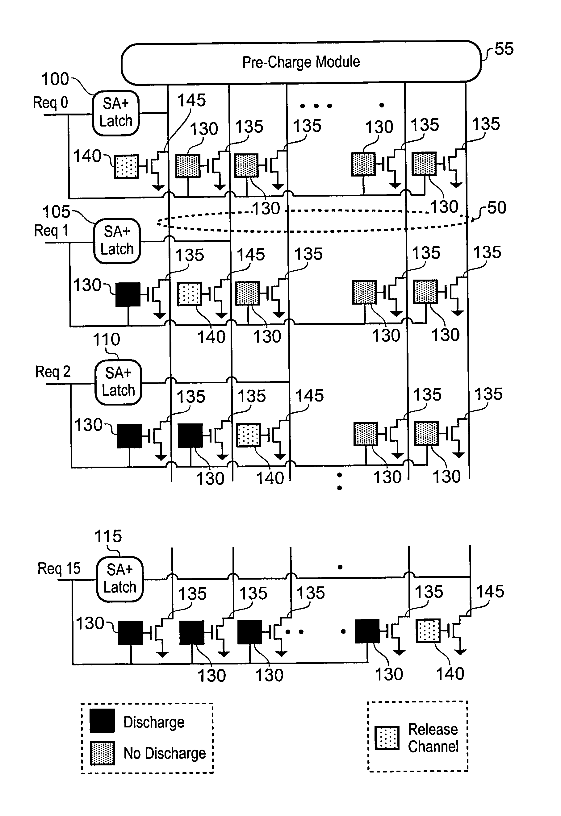
Figure 1 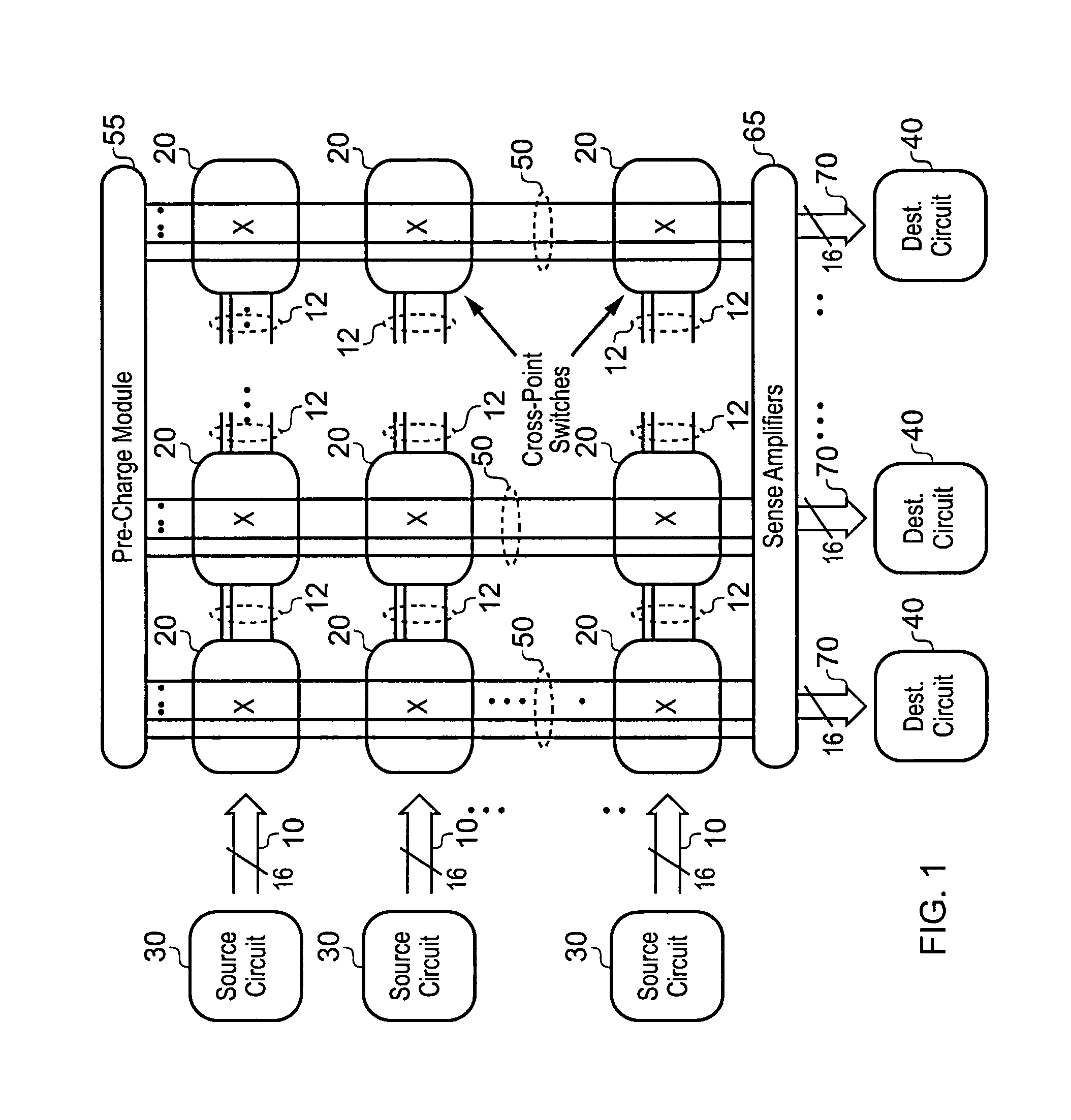
Figure 2 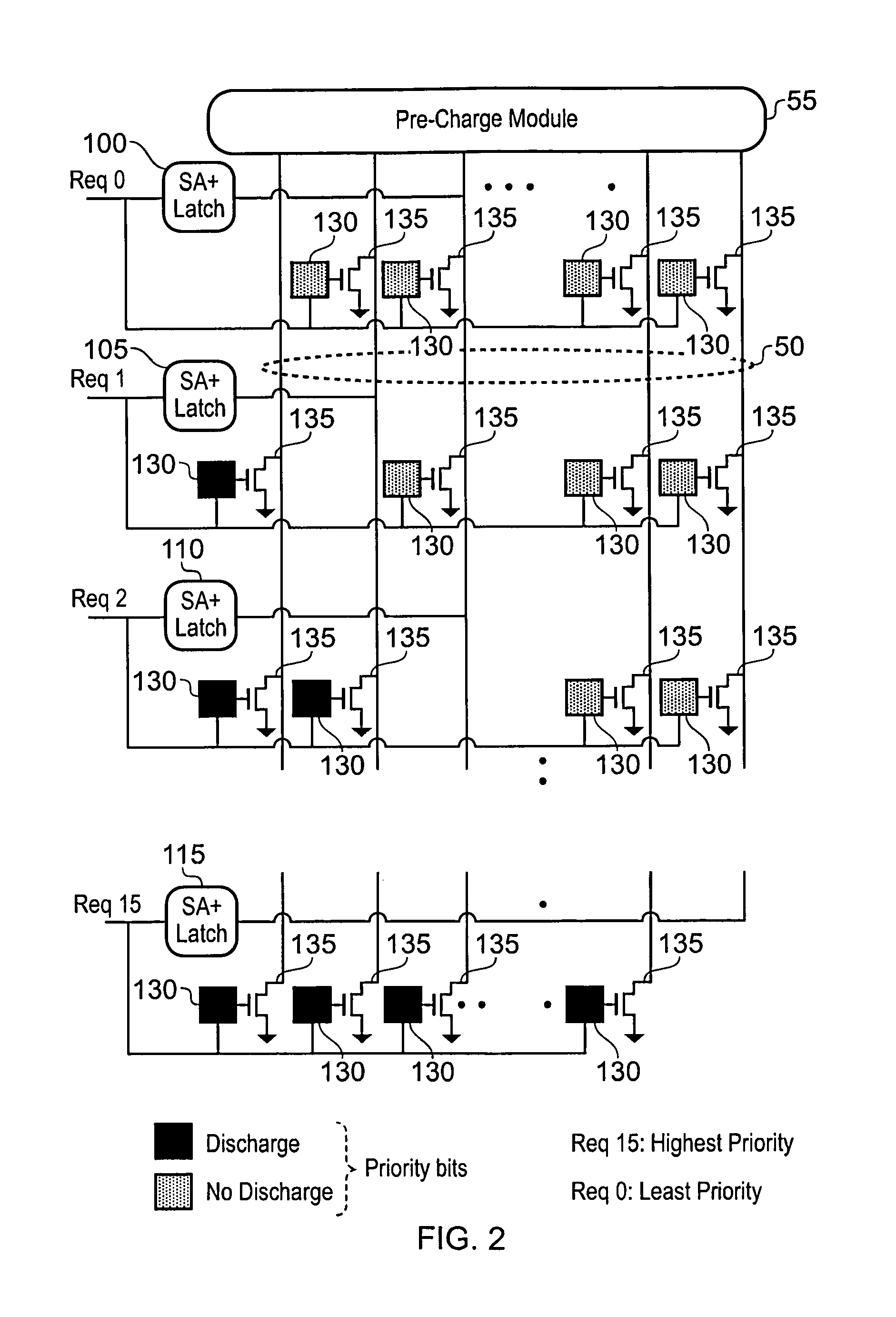
Figure 3
Abstract
Description
[0001] This application is a continuation-in-part of U.S. application Ser. No. 12 / 458,511 filed Jul. 14, 2009 now U.S. Pat. No. 8,230,152, which is a continuation-in-part of U.S. application Ser. No. 12 / 379,191 filed Feb. 13, 2009 now U.S. Pat. No. 8,108,585, the entire contents of each of which are hereby incorporated by reference.BACKGROUND OF THE INVENTION
[0002] 1. Field of the Invention
[0003] The present invention relates to crossbar circuitry for applying an adaptive priority scheme, and a method of operation of such crossbar circuitry.
[0004] 2. Description of the Prior Art
[0005] A crossbar circuit is a switch infrastructure for connecting multiple inputs to multiple outputs in a matrix manner. Accordingly, crossbar circuitry can be used to interconnect a plurality of source circuits and a plurality of destination circuits such that data input to the crossbar circuitry from any of the plurality of source circuits can be output to any of the plurality of destination circuits. Crossba...
Examples
Embodiment Construction
[0098]FIG. 1 illustrates a top-level diagram of a proposed switching fabric, comprising a crossbar circuitry in accordance with one embodiment and a plurality of source circuits and destination circuits connected thereto. The crossbar circuitry includes a plurality of data input paths 12 running in a first direction through the crossbar circuitry, and a plurality of data output paths 50 running in a second direction transverse to the first direction. In the embodiment of FIG. 1, both of these paths are formed by multi-bit buses, and in particular each data input path comprises a plurality of word lines and each data output path comprises a plurality of bit lines.
[0099]At the intersection between each data input path and data output path, a crossbar cell 20 is provided, which is used to selectively route data received on the associated data input path out on the associated data output path. Each crossbar cell includes a configuration storage element for storing the on / off status of e...