
Method and device for operating a trigger device for occupant protection means
a technology for occupant protection and trigger devices, which is applied in the direction of pedestrian/occupant safety arrangements, vehicle components, instruments, etc., can solve the problems of irreparable damage of the trigger device, and achieve the effects of saving valuable energy, saving space, and saving energy
Patent Information
- Authority / Receiving Office
- US · United States
- Patent Type
- Patents(United States)
- Current Assignee / Owner
- Publication Date
- 2017-01-10
Smart Images
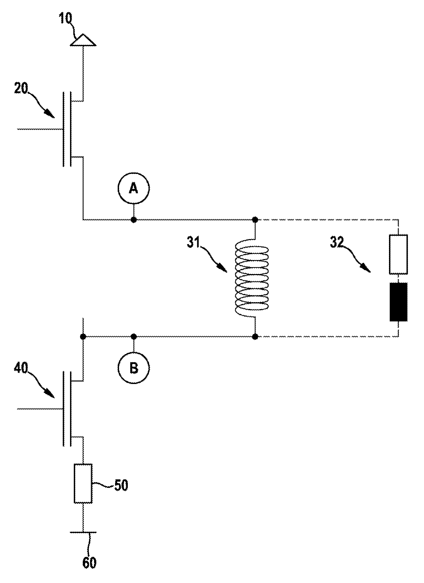
Figure 1 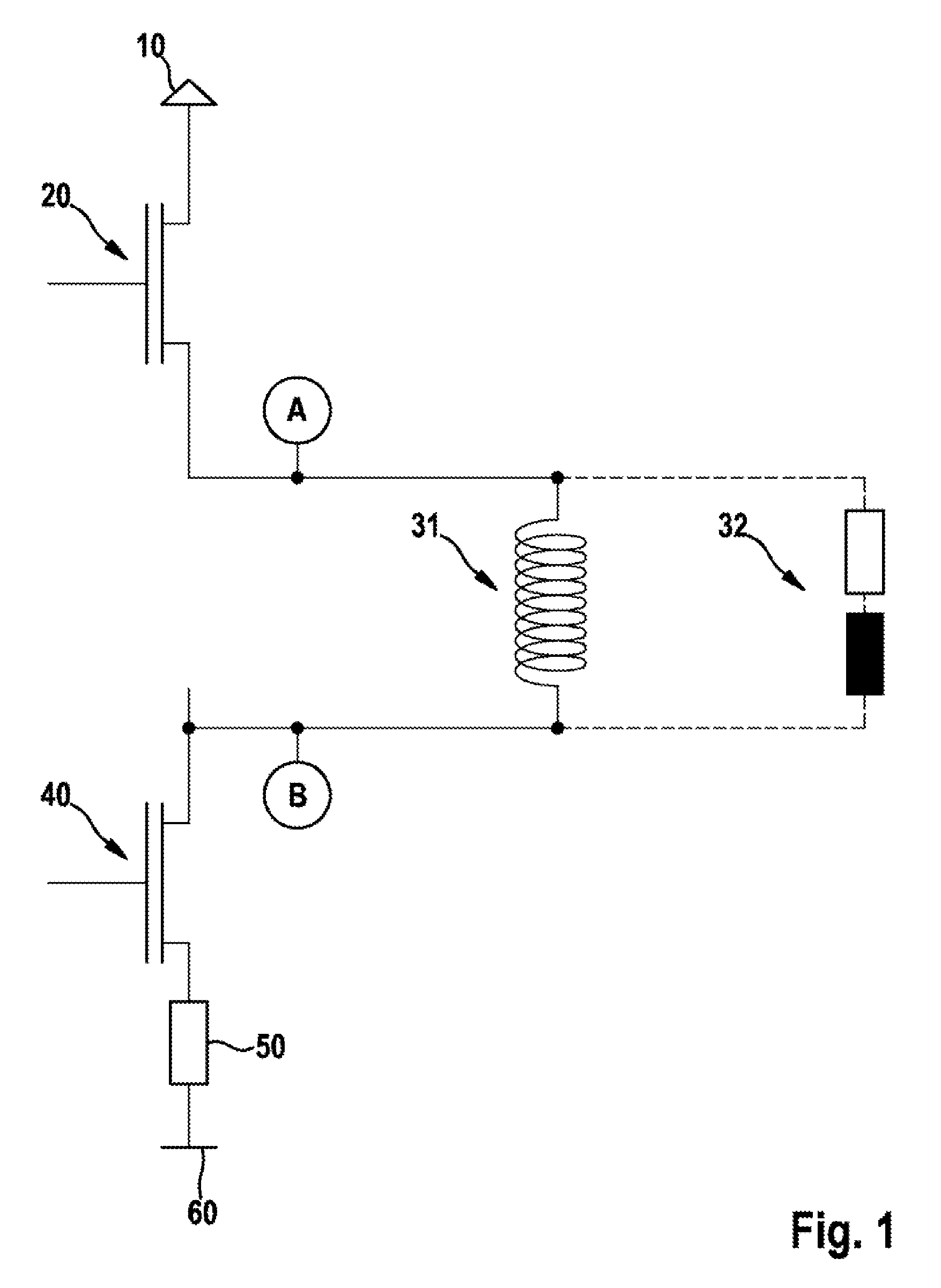
Figure 2 
Figure 3
Abstract
Description
BACKGROUND OF THE INVENTION
[0001] 1. Field of the Invention
[0002] The present invention relates to a method for operating a trigger device for occupant protection means, to a device for triggering occupant protection means, and to a control unit.
[0003] 2. Description of the Related Art
[0004] A number of methods for operating a trigger device for occupant protection means are already known from the related art, in which at least two switches, so-called output stages, are activated for triggering purposes to connect at least one trigger means to a voltage supply.
[0005] Trigger devices for occupant protection means are generally electrical or electronic components. Trigger devices additionally come into play whenever high physical forces act on a vehicle, for example in the instance of a collision. For a wide variety of reasons, there is the possibility that a short circuit forms in the ignition circuit.
[0006] In today's trigger devices for occupant protection means, the output stages are al...
Examples
Embodiment Construction
[0038]FIG. 1 shows a circuit diagram of a trigger device according to one specific embodiment of the present invention. Reference numeral 10 denotes a supply voltage, reference numeral 20 denotes a first switch or a high side switch, reference numeral 31 denotes a pyrotechnic trigger means, reference numeral 32 denotes an inductive trigger means, reference numeral 40 denotes a second switch or a low side switch, reference numeral 50 denotes a (forward slope) resistance RDSon, and reference numeral 60 denotes a ground potential.
[0039]Points A and B indicate locations at which a short circuit to a supply voltage 10 may occur. When a short circuit occurs at point A, it is referred to as a short circuit on high side switch 20. If the short circuit is present with low resistance, it involves a short circuit of Case A. When a short circuit occurs at point B, it is referred to as a short circuit on low side switch 40. If the short circuit is present with low resistance, it involves a short...