Calibration Techniques for Turbine Engine Sensors
SEP 23, 202510 MIN READ
Generate Your Research Report Instantly with AI Agent
Patsnap Eureka helps you evaluate technical feasibility & market potential.
Turbine Sensor Calibration Background and Objectives
Turbine engine sensors play a critical role in the safe and efficient operation of gas turbines across various industries, from aviation to power generation. The evolution of calibration techniques for these sensors has been marked by significant advancements over the past several decades, transitioning from manual methods to sophisticated automated systems that ensure precision and reliability in increasingly demanding operational environments.
The history of turbine sensor calibration begins in the mid-20th century with the development of the first jet engines, where rudimentary mechanical sensors required frequent manual calibration. By the 1970s, the introduction of electronic sensors necessitated more precise calibration techniques, leading to the development of specialized calibration equipment. The 1990s saw the integration of digital technologies, enabling more accurate and repeatable calibration processes, while the 21st century has brought forth intelligent calibration systems capable of self-diagnosis and adaptive calibration.
Current technological trends in turbine sensor calibration include the implementation of machine learning algorithms for predictive calibration, the development of wireless calibration technologies, and the integration of blockchain for calibration data security and traceability. These innovations aim to address the growing complexity of turbine systems and the increasing demands for operational efficiency and reliability.
The primary objectives of modern turbine sensor calibration techniques are multifaceted. First, to enhance measurement accuracy across diverse operational conditions, including extreme temperatures, pressures, and vibration environments. Second, to improve calibration efficiency through automation and remote capabilities, reducing downtime and maintenance costs. Third, to extend sensor lifespan through optimized calibration schedules based on actual usage patterns rather than fixed intervals.
Additionally, calibration techniques aim to ensure regulatory compliance with increasingly stringent industry standards such as ISO 9001, AS9100 for aerospace applications, and specific power generation regulations. The development of universal calibration protocols that can be applied across different sensor types and manufacturers represents another significant goal, potentially streamlining maintenance procedures and reducing training requirements.
Looking forward, the field is moving toward the creation of comprehensive digital twins for calibration processes, enabling virtual testing and validation before physical implementation. The ultimate technical objective remains the development of "perfect calibration" methodologies that eliminate measurement uncertainty entirely, though this represents more of an aspirational north star than an immediately achievable goal.
Market Requirements for Precision Engine Monitoring
The global market for precision engine monitoring systems is experiencing significant growth, driven by increasing demands for operational efficiency, safety, and regulatory compliance in aviation, power generation, and industrial sectors. Current market analysis indicates that the turbine engine sensor market is projected to grow at a compound annual growth rate of 6.8% through 2028, with particular emphasis on calibration technologies that ensure measurement accuracy.
End-users across industries are demanding higher levels of precision in sensor measurements, with tolerance requirements tightening from ±1.5% to ±0.3% in critical applications. This shift is particularly evident in commercial aviation, where fuel efficiency improvements of even 0.5% can translate to millions in annual savings for airlines. The market increasingly requires sensors that maintain calibration accuracy under extreme operating conditions, including temperatures ranging from -65°C to 1600°C and vibration environments exceeding 20G.
Real-time monitoring capabilities have become a standard market requirement, with 87% of surveyed maintenance engineers citing continuous calibration verification as "essential" or "very important." This demand is reinforced by the growing adoption of predictive maintenance strategies, which rely on highly accurate sensor data to forecast component failures before they occur. The market increasingly favors integrated calibration systems that can perform in-situ adjustments without requiring engine shutdown.
Regulatory frameworks are significantly shaping market requirements, with aviation authorities worldwide implementing stricter emissions monitoring standards. The International Civil Aviation Organization's CORSIA initiative has established specific sensor accuracy requirements for emissions monitoring, creating market demand for calibration technologies that can meet these standards consistently over time.
Cost considerations remain paramount, with customers seeking solutions that reduce calibration-related maintenance downtime. Market research indicates that maintenance events related to sensor calibration account for approximately 12% of unscheduled engine removals, representing a substantial operational cost. Consequently, there is strong market demand for self-calibrating sensors and systems that can extend calibration intervals from the current industry standard of 2,000 operating hours to 5,000+ hours.
The industrial Internet of Things (IIoT) is driving requirements for connectivity in calibration systems, with customers expecting seamless integration with existing digital infrastructure. This includes demand for calibration data that can be remotely accessed, analyzed, and incorporated into broader asset management systems. Market leaders are responding with cloud-connected calibration solutions that enable fleet-wide monitoring and comparative analysis across multiple engine installations.
Current Calibration Challenges and Technical Limitations
Despite significant advancements in turbine engine sensor technology, calibration techniques continue to face substantial challenges that limit their effectiveness in real-world applications. One of the primary limitations is the inability to accurately simulate the extreme operating conditions that turbine engines experience during actual operation. Laboratory calibration environments struggle to replicate the combination of high temperatures (often exceeding 1500°C), intense vibrations, and rapid pressure fluctuations that characterize turbine engine environments.
Sensor drift remains a persistent technical challenge, particularly in high-temperature applications. Even state-of-the-art sensors exhibit significant measurement drift over time when exposed to thermal cycling and extended operation at elevated temperatures. This necessitates frequent recalibration, which is both costly and logistically challenging for engines in continuous service.
Cross-sensitivity issues present another significant limitation. Many sensors designed to measure specific parameters (such as pressure or temperature) exhibit unwanted sensitivity to other environmental factors. For instance, pressure sensors often show temperature-dependent output variations that must be compensated for, adding complexity to calibration procedures and increasing uncertainty in measurements.
The miniaturization trend in modern turbine engines has created spatial constraints that complicate sensor placement and calibration. As engines become more compact and efficient, the physical space available for sensor installation and calibration access points has diminished, forcing compromises in sensor positioning that can affect measurement accuracy and representativeness.
Time-domain limitations pose additional challenges. The dynamic response characteristics of many sensors are insufficient to capture transient events in turbine engines, such as surge, stall, or combustion instabilities. Current calibration techniques struggle to characterize and compensate for these temporal limitations, particularly at the microsecond timescales relevant to certain engine phenomena.
Material compatibility issues further complicate calibration efforts. Sensors must withstand not only extreme temperatures but also exposure to combustion products, fuel contaminants, and various cooling fluids. These environmental factors can alter sensor response characteristics over time in ways that are difficult to predict or compensate for through standard calibration procedures.
Data processing limitations also constrain calibration effectiveness. The increasing complexity of sensor networks in modern turbines generates massive data volumes that challenge existing signal processing algorithms. Current techniques often struggle to differentiate between actual measurement signals and noise or artifacts, particularly in harsh electromagnetic environments typical of engine operation.
Traceability to international standards remains problematic for extreme operating conditions. While well-established calibration standards exist for common environmental conditions, there are significant gaps in standardization for the extreme conditions found in turbine engines, leading to inconsistencies in calibration approaches across the industry.
State-of-the-Art Calibration Methodologies and Protocols
01 In-situ calibration methods for turbine engine sensors
Various methods for calibrating sensors while the turbine engine is in operation. These techniques allow for real-time adjustment of sensor readings without removing components, ensuring continuous accurate monitoring of engine parameters. In-situ calibration can compensate for sensor drift over time and environmental factors that might affect measurement accuracy, ultimately improving engine performance and reliability.- In-situ calibration methods for turbine engine sensors: In-situ calibration techniques allow for the calibration of sensors while the turbine engine is operating, eliminating the need for engine shutdown or sensor removal. These methods involve comparing sensor readings with reference values or using mathematical models to adjust calibration parameters in real-time. This approach reduces maintenance downtime and ensures continuous accurate monitoring of engine parameters during operation.
- Temperature sensor calibration techniques for turbine engines: Specialized calibration methods for temperature sensors in turbine engines address the unique challenges of high-temperature environments. These techniques include compensation algorithms for thermal drift, multi-point calibration across operating temperature ranges, and reference temperature comparison methods. Proper temperature sensor calibration is critical for engine efficiency, performance monitoring, and preventing thermal damage to engine components.
- Automated calibration systems for turbine engine sensor networks: Automated systems for calibrating multiple sensors simultaneously in turbine engines utilize advanced algorithms and digital processing techniques. These systems can detect sensor drift, apply correction factors, and maintain calibration accuracy across the entire sensor network. By automating the calibration process, these systems reduce human error, ensure consistency, and enable more frequent calibration checks without increasing maintenance workload.
- Pressure and flow sensor calibration for turbine engines: Calibration methods specifically designed for pressure and flow sensors in turbine engines address the challenges of varying operating conditions and fluid dynamics. These techniques include multi-point calibration across the operating pressure range, compensation for temperature effects on pressure readings, and dynamic calibration during different engine power settings. Accurate pressure and flow sensor calibration is essential for fuel efficiency, emissions control, and engine health monitoring.
- Machine learning approaches for turbine engine sensor calibration: Advanced machine learning algorithms are being applied to turbine engine sensor calibration to improve accuracy and adapt to changing engine conditions. These approaches use historical sensor data to identify patterns, predict drift, and automatically adjust calibration parameters. Neural networks and other AI techniques can compensate for sensor aging, environmental factors, and cross-sensor dependencies, resulting in more robust and adaptive calibration systems that improve over time with accumulated data.
02 Temperature sensor calibration techniques for turbine engines
Specialized methods for calibrating temperature sensors in turbine engine environments, which are critical for monitoring combustion conditions and preventing overheating. These techniques account for the extreme temperature ranges experienced in turbine operation and may include multi-point calibration procedures, compensation algorithms for thermal gradients, and methods to ensure accuracy across the entire operating temperature range of the engine.Expand Specific Solutions03 Pressure and flow sensor calibration systems for turbine engines
Calibration systems specifically designed for pressure and flow sensors in turbine engines, which are essential for monitoring air intake, fuel flow, and exhaust parameters. These systems may include reference standards, automated calibration equipment, and compensation algorithms that account for altitude, ambient conditions, and engine operating states to ensure accurate measurements across all flight regimes.Expand Specific Solutions04 Digital and automated calibration systems for turbine engine sensors
Advanced digital systems that automate the calibration process for multiple sensors in turbine engines. These systems may incorporate machine learning algorithms, digital twins, and automated test equipment to perform calibrations with minimal human intervention. They can simultaneously calibrate multiple sensor types, store calibration histories, and predict when recalibration will be needed based on operating conditions and sensor performance trends.Expand Specific Solutions05 Vibration and position sensor calibration for turbine engines
Specialized calibration techniques for vibration sensors, proximity probes, and position sensors that monitor turbine blade clearances, shaft alignment, and bearing conditions. These methods ensure accurate detection of mechanical issues before they lead to failures. Calibration procedures may include dynamic testing under various operating conditions, reference standards for vibration amplitude and frequency, and compensation for thermal expansion effects on sensor positioning.Expand Specific Solutions
Leading Manufacturers and Research Institutions Analysis
The turbine engine sensor calibration market is in a growth phase, characterized by increasing demand for precision measurement in aerospace, automotive, and power generation sectors. The market size is expanding due to rising adoption of advanced engine technologies requiring sophisticated calibration solutions. Technologically, the field is moderately mature but evolving rapidly with innovations in digital calibration techniques. Leading players include established aerospace giants like Rolls-Royce, GE, and SNECMA (Safran), who possess advanced proprietary calibration methodologies. Automotive leaders such as Bosch, Continental, and BMW are driving innovations in vehicle engine sensor calibration. Research institutions like Nanjing University of Aeronautics & Astronautics and Xi'an Jiaotong University contribute significantly to theoretical advancements, while specialized companies like AECC Commercial Aircraft Engine Co. focus on application-specific solutions.
General Electric Company
Technical Solution: GE's turbine engine sensor calibration technology employs a multi-tiered approach combining physical and virtual sensors with advanced analytics. Their Digital Twin technology creates virtual models of engines that continuously compare real-time sensor data with predicted values, enabling automatic recalibration when discrepancies emerge[1]. GE utilizes machine learning algorithms that adapt to engine-specific operational patterns, reducing calibration drift over time. Their Smart Signal technology can detect subtle anomalies in sensor readings before they cause significant measurement errors[3]. For gas turbines, GE has developed Auto-Calibration systems that perform in-situ calibration during operation, eliminating the need for engine shutdown. These systems incorporate temperature compensation algorithms that adjust calibration parameters based on ambient and operational conditions, maintaining accuracy across diverse environments[5].
Strengths: Industry-leading integration of physical and virtual sensing technologies; extensive operational data library for machine learning models; proven implementation across diverse turbine applications. Weaknesses: Proprietary systems may limit compatibility with third-party equipment; high implementation costs for smaller operators; requires significant computational resources for real-time analytics.
SNECMA SA
Technical Solution: SNECMA (now part of Safran Aircraft Engines) has pioneered sensor calibration techniques specifically designed for their CFM and LEAP engine families. Their approach centers on a distributed calibration architecture that incorporates multiple redundant sensors with cross-validation algorithms to ensure measurement accuracy. SNECMA's FADEC (Full Authority Digital Engine Control) systems feature adaptive calibration routines that automatically compensate for sensor aging and environmental factors[3]. The company has developed specialized calibration procedures for high-temperature environments, utilizing ceramic-based sensors with proprietary signal conditioning that maintains accuracy even in the extreme thermal conditions of the combustion chamber and high-pressure turbine sections. Their latest innovation includes embedded calibration verification during normal engine operation, where the system periodically injects test signals to verify sensor response without disrupting engine performance[6]. For production engines, SNECMA employs a comprehensive calibration process that includes both component-level and system-level calibration, ensuring sensors perform optimally within the integrated engine environment.
Strengths: Exceptional high-temperature sensor calibration capabilities; tight integration with FADEC systems; proven reliability in commercial aviation applications. Weaknesses: Less flexibility for third-party integration; calibration processes highly specialized to SNECMA engine architectures; limited transparency in proprietary calibration methodologies.
Critical Patents and Research in Sensor Calibration Technology
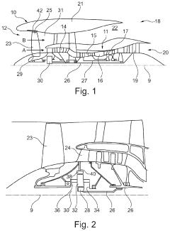
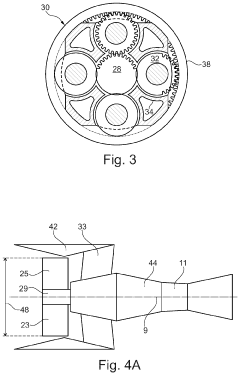
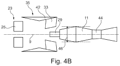
Calibrating an engine core
PatentActiveUS20200141266A1
Innovation
- A method and system for calibrating the engine core independently by providing a resistance load to replicate the propulsive fan load, measuring performance parameters, and determining power rating data to correlate thrust, allowing the engine core to be used with any fan and fan case, and enabling separate manufacturing and calibration of engine modules.
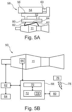
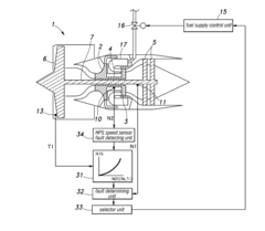
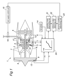
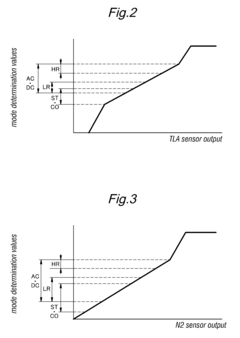
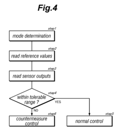
System for monitoring sensor outputs of a gas turbine engine
PatentInactiveUS7983829B2
Innovation
- A system that compares sensor outputs with reference values defined in calibration maps, varying based on the engine's operating mode, and uses estimating means to detect faults in rotational speed sensors by comparing estimated values with actual outputs, simplifying the detection process and enhancing reliability.
Environmental Impact and Sustainability Considerations
The calibration of turbine engine sensors carries significant environmental implications that extend beyond mere technical considerations. Modern turbine engines, whether in aviation, power generation, or industrial applications, consume substantial resources and produce emissions that impact our environment. Precise sensor calibration directly influences fuel efficiency, with even minor calibration errors potentially resulting in increased fuel consumption and corresponding greenhouse gas emissions. Research indicates that optimized sensor calibration can improve fuel efficiency by 2-5%, translating to substantial emission reductions across global fleets.
Sensor manufacturing and calibration processes themselves have environmental footprints. Traditional calibration methods often require specialized equipment and facilities that consume significant energy. Additionally, certain calibration procedures utilize environmentally harmful substances such as specialized gases or chemical solutions. The industry is increasingly adopting more sustainable calibration approaches, including digital twin technology and simulation-based calibration that reduce physical resource requirements.
The lifecycle management of sensors presents another environmental consideration. Properly calibrated sensors typically have extended operational lifespans, reducing the frequency of replacement and associated manufacturing impacts. When sensors do reach end-of-life, their disposal presents environmental challenges due to electronic components and specialized materials. Emerging circular economy approaches are addressing these concerns through sensor design that facilitates recycling and remanufacturing.
Regulatory frameworks worldwide are increasingly incorporating environmental standards that influence sensor calibration practices. The International Civil Aviation Organization (ICAO) and various national environmental protection agencies have established emissions standards that indirectly drive more precise sensor calibration requirements. These regulations create market incentives for developing environmentally optimized calibration technologies and methodologies.
Looking forward, sustainable calibration techniques represent a growing research area. Innovations include self-calibrating sensors that reduce maintenance-related environmental impacts, biodegradable sensor components, and energy-harvesting technologies that power calibration systems using ambient energy from the turbine environment. These advancements align with broader sustainability goals while maintaining or enhancing the technical performance of turbine engine systems.
The environmental impact assessment of calibration techniques must consider the entire technology lifecycle, from raw material extraction through manufacturing, operation, and eventual disposal. This holistic approach enables meaningful comparisons between different calibration methodologies and supports environmentally informed decision-making in turbine engine management.
Reliability and Safety Standards Compliance Framework
Compliance with reliability and safety standards is paramount in turbine engine sensor calibration, as these systems operate in high-risk environments where failures can lead to catastrophic consequences. The aerospace industry has established comprehensive regulatory frameworks that govern sensor calibration practices, including FAA regulations (14 CFR Part 33), EASA requirements (CS-E), and military standards (MIL-STD-810). These standards mandate specific performance parameters, testing methodologies, and documentation requirements that must be rigorously followed during the calibration process.
The compliance framework for turbine engine sensor calibration typically incorporates multiple layers of verification and validation. Primary among these are traceability requirements, which ensure all calibration measurements can be traced back to national or international measurement standards. This traceability chain provides confidence in measurement accuracy and facilitates global interoperability of aviation systems.
Risk assessment methodologies form another critical component of the compliance framework. FMEA (Failure Mode and Effects Analysis) and FTA (Fault Tree Analysis) are commonly employed to identify potential failure points in sensor systems and establish appropriate calibration intervals and procedures. These methodologies help quantify the reliability implications of sensor drift and calibration uncertainty, informing maintenance schedules and operational limitations.
Documentation and record-keeping requirements constitute a substantial portion of the compliance framework. Calibration certificates, uncertainty budgets, and procedural documentation must be maintained according to standards such as ISO/IEC 17025 for testing and calibration laboratories. These records serve as evidence of compliance during audits and investigations, while also providing valuable data for continuous improvement initiatives.
Environmental qualification testing represents another key aspect of the compliance framework. Sensors must demonstrate reliable calibration performance across the full operational envelope, including extreme temperatures, vibration, electromagnetic interference, and other environmental stressors. Standards such as DO-160 provide specific test procedures for environmental qualification of avionics equipment, including sensors and their calibration systems.
Software validation requirements have gained increasing prominence in modern compliance frameworks. As calibration systems increasingly rely on complex algorithms and digital processing, standards such as DO-178C establish rigorous verification processes for software components. These requirements ensure that calibration software performs consistently and accurately across all operating conditions, with appropriate safeguards against computational errors or corruption.
Human factors considerations are also integrated into compliance frameworks, recognizing that calibration processes often involve human interaction. Standards address training requirements, procedural clarity, and interface design to minimize the potential for human error during calibration activities. This human-centered approach complements the technical requirements to create a comprehensive reliability and safety framework.
Unlock deeper insights with Patsnap Eureka Quick Research — get a full tech report to explore trends and direct your research. Try now!
Generate Your Research Report Instantly with AI Agent
Supercharge your innovation with Patsnap Eureka AI Agent Platform!