

How to Test Solid-State Relay for Voltage Drop in Systems
SEP 19, 20259 MIN READ
Generate Your Research Report Instantly with AI Agent
Patsnap Eureka helps you evaluate technical feasibility & market potential.
Solid-State Relay Testing Background and Objectives
Solid-state relays (SSRs) have evolved significantly since their introduction in the 1970s as alternatives to electromechanical relays. These semiconductor-based switching devices have transformed industrial automation, power distribution systems, and consumer electronics by offering enhanced reliability, faster switching speeds, and elimination of mechanical wear. The technological progression of SSRs has been marked by improvements in semiconductor materials, integration capabilities, and thermal management techniques.
The voltage drop across an SSR represents a critical performance parameter that directly impacts system efficiency, heat generation, and overall reliability. As power systems become increasingly complex and energy efficiency standards more stringent, the accurate measurement and optimization of voltage drop in SSRs has gained paramount importance across industries ranging from automotive to renewable energy systems.
Current industry standards, including IEC 62314 and UL 508, establish baseline requirements for SSR performance, but testing methodologies continue to evolve as applications demand greater precision and reliability. The technological trajectory indicates a growing need for standardized, yet adaptable testing protocols that can accommodate the diverse range of SSR implementations in modern systems.
The primary objective of SSR voltage drop testing is to ensure optimal performance under various load conditions while maintaining system integrity. This involves developing comprehensive testing methodologies that can accurately measure voltage drops across different SSR types (AC, DC, and hybrid), under varying load profiles, and across temperature ranges that reflect real-world operating environments.
Secondary objectives include identifying potential failure modes related to excessive voltage drop, establishing predictive maintenance protocols based on voltage drop trends, and developing comparative benchmarks for different SSR technologies and manufacturers. These objectives align with broader industry goals of improving energy efficiency, extending component lifespan, and reducing system downtime.
The evolution of testing equipment has paralleled SSR development, with modern instrumentation offering unprecedented precision in measuring voltage drops in the millivolt range. Digital oscilloscopes, specialized load testers, and thermal imaging systems now provide multidimensional insights into SSR performance that were previously unattainable. These technological advancements enable more sophisticated analysis of voltage drop characteristics under dynamic operating conditions.
Looking forward, the integration of IoT capabilities and machine learning algorithms into SSR testing protocols represents the next frontier in this field. These technologies promise to enable real-time monitoring, predictive analytics, and automated optimization of SSR performance parameters, including voltage drop, in increasingly complex and distributed power systems.
Market Requirements for Voltage Drop Testing
The market for solid-state relay (SSR) voltage drop testing equipment is experiencing significant growth driven by the increasing adoption of SSRs across multiple industries. Industrial automation represents the largest market segment, with manufacturing facilities requiring precise voltage drop testing to ensure operational reliability and prevent costly downtime. According to industry analyses, manufacturing downtime costs can exceed $10,000 per hour in medium-sized facilities, making reliable SSR performance critical.
Power distribution and energy management systems constitute another major market segment demanding advanced voltage drop testing solutions. As smart grid technologies proliferate, the need for accurate SSR performance verification has intensified, particularly in applications where voltage stability directly impacts system efficiency and safety. Utility companies are increasingly implementing predictive maintenance protocols that necessitate regular SSR voltage drop testing.
The healthcare sector presents a rapidly growing market for SSR testing equipment, particularly in critical care environments where power reliability directly impacts patient outcomes. Medical device manufacturers must comply with stringent regulatory standards such as IEC 60601, which mandates comprehensive testing of electrical components including SSRs. Testing solutions that can document compliance with these standards command premium pricing in this segment.
Transportation systems, particularly in railway and aviation applications, require SSR testing equipment capable of operating in harsh environmental conditions. These sectors prioritize testing solutions that can verify SSR performance across wide temperature ranges and under vibration stress, reflecting real-world operating conditions.
Market research indicates a strong preference for automated testing solutions that can be integrated into existing quality control processes. End users consistently express requirements for testing equipment that provides digital documentation capabilities, remote monitoring functionality, and integration with industrial IoT platforms. The ability to perform non-intrusive testing without system disconnection represents a significant market differentiator.
Testing speed has emerged as a critical market requirement, with manufacturers seeking solutions that minimize production line interruptions. Concurrent testing capabilities that can evaluate multiple SSRs simultaneously command higher market valuations. Additionally, there is growing demand for portable testing equipment that enables field technicians to perform on-site diagnostics without specialized training.
Cost sensitivity varies significantly across market segments, with critical infrastructure applications prioritizing accuracy and reliability over initial equipment cost. Conversely, general manufacturing applications demonstrate greater price sensitivity, creating market opportunities for tiered testing solutions with varying levels of precision and functionality.
Current Challenges in SSR Voltage Drop Measurement
Despite significant advancements in solid-state relay (SSR) technology, measuring voltage drop accurately remains a persistent challenge for engineers and technicians. The primary difficulty stems from the inherent characteristics of semiconductor materials used in SSRs, which exhibit non-linear behavior under varying load conditions. Traditional measurement techniques often fail to capture the dynamic nature of voltage drops that occur during switching operations, particularly in high-frequency applications.
One major challenge is the temperature dependency of SSR performance. As SSRs heat up during operation, their internal resistance changes, directly affecting the voltage drop across the device. This creates a moving target for measurement protocols, as readings taken at different thermal states may vary significantly. Current testing methodologies struggle to account for these thermal variations in real-time, leading to inconsistent results across testing sessions.
The lack of standardized testing procedures specifically designed for SSR voltage drop measurement compounds these difficulties. While standards exist for mechanical relays, the unique characteristics of solid-state devices require specialized approaches that many industry standards have not fully addressed. This regulatory gap has resulted in manufacturers developing proprietary testing methods, making cross-product comparisons challenging for system integrators.
Measurement accuracy is further complicated by the presence of transient voltage spikes during switching operations. These momentary fluctuations, often lasting only microseconds, can be missed by conventional measurement equipment but may significantly impact system performance. Capturing these transients requires sophisticated oscilloscopes with high sampling rates, which are not always available in standard testing environments.
In industrial applications, electromagnetic interference (EMI) from surrounding equipment introduces noise into measurement circuits, obscuring the true voltage drop values. This is particularly problematic in factory automation systems where multiple power switching devices operate in close proximity. Current filtering techniques are often insufficient to completely eliminate this interference, leading to measurement uncertainties.
The miniaturization trend in modern electronics has created additional challenges for voltage drop testing. As SSRs become smaller and are integrated into more compact systems, physical access for test probes becomes restricted. This limited accessibility makes it difficult to perform direct measurements at the exact points needed for accurate voltage drop assessment, forcing engineers to rely on indirect measurement methods with inherent inaccuracies.
Finally, there is a growing need for in-situ testing capabilities that can monitor SSR voltage drop during actual system operation without disrupting functionality. Current testing approaches typically require taking systems offline or creating artificial test conditions that may not accurately reflect real-world performance parameters.
Standard Testing Protocols and Procedures
01 Voltage drop reduction techniques in solid-state relays
Various techniques can be employed to reduce voltage drop in solid-state relays, including optimized semiconductor materials, improved junction designs, and enhanced thermal management. These approaches minimize power losses during conduction and improve overall efficiency. Advanced semiconductor materials with lower resistance characteristics help decrease the forward voltage drop across the relay, resulting in better performance and reduced heat generation during operation.- Voltage drop reduction techniques in solid-state relays: Various techniques can be employed to reduce voltage drop in solid-state relays, including optimized semiconductor materials, improved junction designs, and enhanced thermal management. These approaches minimize power losses during conduction and improve overall efficiency. Advanced semiconductor fabrication processes and materials selection can significantly reduce the on-state resistance, which is directly related to voltage drop across the relay.
- Circuit configurations to manage voltage drop: Specific circuit configurations can be implemented to manage and compensate for voltage drop in solid-state relays. These include parallel transistor arrangements, feedback control loops, and voltage compensation circuits. By monitoring the voltage across the relay and dynamically adjusting the gate drive or control signals, these configurations maintain consistent output voltage regardless of load conditions or temperature variations.
- Thermal management solutions for voltage drop control: Thermal management plays a crucial role in controlling voltage drop in solid-state relays. As temperature increases, semiconductor resistance typically increases, leading to higher voltage drops. Solutions include integrated heat sinks, thermal interface materials, active cooling systems, and temperature-compensated control circuits that adjust operation based on thermal conditions to maintain consistent performance across varying temperatures.
- Advanced semiconductor materials and structures: The use of advanced semiconductor materials and structures can significantly reduce voltage drop in solid-state relays. Wide bandgap semiconductors such as silicon carbide (SiC) and gallium nitride (GaN) offer lower on-resistance compared to traditional silicon. Additionally, specialized junction structures, trench designs, and doping profiles can optimize carrier flow and reduce resistive losses during conduction states.
- Protection and monitoring systems for voltage drop management: Protection and monitoring systems are integrated into solid-state relays to manage voltage drop effects. These systems include overvoltage protection circuits, current limiting features, and real-time monitoring of operating parameters. By continuously measuring voltage drop across the relay and implementing protective measures when thresholds are exceeded, these systems prevent damage to both the relay and connected equipment while maintaining optimal performance.
02 Circuit configurations to manage voltage drop
Specific circuit configurations can be implemented to manage and compensate for voltage drop in solid-state relays. These include parallel transistor arrangements, feedback control loops, and voltage compensation circuits. By distributing current across multiple switching elements or implementing active compensation mechanisms, the effective voltage drop across the relay can be minimized. These circuit designs help maintain consistent output voltage levels despite inherent semiconductor junction voltage drops.Expand Specific Solutions03 Thermal management solutions for voltage drop issues
Thermal management plays a crucial role in controlling voltage drop in solid-state relays. As temperature increases, semiconductor resistance typically increases, leading to higher voltage drops. Solutions include improved heat sinking, thermal interface materials, active cooling systems, and temperature-compensated designs. By maintaining lower operating temperatures, the voltage drop characteristics of the relay can be kept within optimal ranges, ensuring reliable operation and extended device lifetime.Expand Specific Solutions04 Advanced semiconductor materials and structures
The use of advanced semiconductor materials and structures significantly impacts voltage drop in solid-state relays. Materials such as silicon carbide (SiC) and gallium nitride (GaN) offer lower on-state resistance compared to traditional silicon, resulting in reduced voltage drop. Additionally, specialized junction structures, doping profiles, and multi-layer semiconductor designs can optimize current flow and minimize resistive losses, leading to improved relay performance with lower voltage drop during conduction.Expand Specific Solutions05 Protection and monitoring systems for voltage drop
Protection and monitoring systems are essential for managing voltage drop effects in solid-state relay applications. These include overvoltage protection circuits, current limiting features, and real-time monitoring of voltage drop parameters. By implementing these systems, potential damage from excessive voltage drop can be prevented, and relay performance can be optimized. Diagnostic capabilities allow for early detection of increasing voltage drop, which might indicate relay degradation or system issues requiring maintenance.Expand Specific Solutions
Leading Manufacturers and Test Equipment Providers
The solid-state relay (SSR) voltage drop testing market is currently in a growth phase, driven by increasing adoption of automation and smart grid technologies. The market size is expanding rapidly, with an estimated annual growth rate of 5-7% globally. From a technical maturity perspective, the field is evolving with established players like Littelfuse, TE Connectivity, and Schneider Electric leading innovation in precision testing methodologies. State Grid Corporation of China and Guangdong Power Grid are driving implementation in large-scale power infrastructure, while automotive manufacturers like Toyota and Hyundai Mobis are advancing applications in vehicle electronics. Research collaboration between industry and academic institutions such as South China University of Technology and Indian Institute of Technology Roorkee is accelerating development of more efficient testing protocols and standards for next-generation solid-state relay systems.
Littelfuse, Inc.
Technical Solution: Littelfuse has developed comprehensive testing methodologies for solid-state relay (SSR) voltage drop assessment that combine both laboratory and field testing approaches. Their technical solution incorporates automated test equipment (ATE) that applies controlled loads while measuring voltage differentials across SSR terminals with precision in the millivolt range. The company employs a four-wire Kelvin connection method to eliminate lead resistance effects, ensuring accurate voltage drop measurements[1]. Their testing protocol includes thermal cycling to evaluate how temperature fluctuations affect SSR performance, as voltage drop characteristics can vary significantly with temperature. Littelfuse also implements pulse width modulation (PWM) signal testing to assess SSR behavior under dynamic switching conditions, which is critical for applications with variable loads. Their advanced diagnostic systems can detect anomalies in switching characteristics that might indicate impending failure before voltage drop increases to problematic levels.
Strengths: Highly accurate measurement capabilities with specialized equipment designed specifically for SSR testing; comprehensive thermal performance evaluation; established industry expertise in protection components. Weaknesses: Their testing solutions often require specialized equipment that may be cost-prohibitive for smaller operations; some testing protocols may be overly complex for basic field diagnostics.
TE Connectivity Corp.
Technical Solution: TE Connectivity has developed specialized SSR testing technology focused on connector and relay interface quality assessment. Their approach addresses voltage drop testing as part of a broader reliability assessment framework for electronic systems. TE's solution incorporates precision measurement circuits that can detect voltage drops as low as 10 microvolts across SSR contacts, enabling early identification of degradation. Their testing methodology includes both static and dynamic load testing, with particular emphasis on inrush current handling capabilities that can affect SSR performance. TE has pioneered accelerated life testing protocols specifically for SSRs that correlate voltage drop increases with remaining useful life, allowing for predictive maintenance scheduling. Their testing systems employ specialized fixtures that ensure consistent contact pressure and alignment during measurement, eliminating variables that could affect test accuracy. TE also provides environmental testing capabilities that assess SSR voltage drop performance under extreme conditions including high humidity, salt fog exposure, and vibration, which are critical factors in transportation and industrial applications where SSRs must maintain low voltage drops despite harsh operating environments.
Strengths: Exceptional measurement precision; comprehensive environmental testing capabilities; extensive experience with connector and interface technologies that complement SSR testing. Weaknesses: Solutions may focus more on laboratory and production testing than field diagnostics; specialized equipment requirements may limit accessibility for some users.
Advanced Measurement Techniques and Innovations
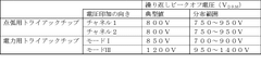
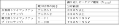
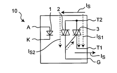
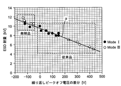
Solid state relay, power triac chip, and method for testing solid state relay
PatentWO2016194436A1
Innovation
- The design of the solid-state relay includes a power triac chip with reduced bidirectional repetitive peak-off voltage imbalance by setting the difference between mode I and mode III peak-off voltages within a predetermined tolerance range, ensuring the power triac chip's peak-off voltage is lower than the ignition triac chip's, and implementing a testing method to ensure products meet specific peak-off voltage standards for enhanced ESD resistance.
Relay contact voltage drop test fixture
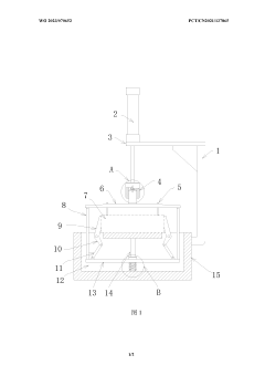
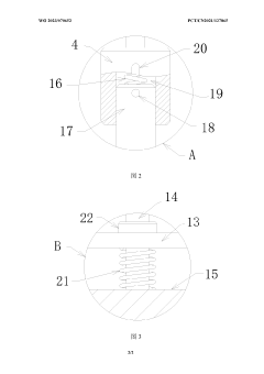
PatentWO2023070652A1
Innovation
- A relay contact voltage drop test fixture is designed, which uses a cylinder to drive the test plate to move downward to make the test column contact the relay contact, and drives the clamping arm to clamp the relay through the drive assembly to ensure test accuracy and convenient operation. At the same time, it utilizes The buffer spring and return spring realize the automatic clamping function.
Safety Standards and Compliance Requirements
Testing solid-state relays (SSRs) for voltage drop must adhere to comprehensive safety standards and compliance requirements established by international and regional regulatory bodies. The International Electrotechnical Commission (IEC) provides the foundational standards, particularly IEC 60947-4-3 for semiconductor controllers and contactors for non-motor loads, which specifies testing methodologies and acceptable voltage drop parameters for SSRs in various applications.
In North America, Underwriters Laboratories (UL) standard UL 508 for industrial control equipment mandates specific voltage drop testing procedures for solid-state switching devices. These tests must be conducted at rated current and temperature to ensure the SSR performs within acceptable parameters under normal operating conditions. Additionally, UL 1577 addresses optical isolators often used in SSR designs, requiring isolation voltage testing to prevent hazardous voltage transfer.
European compliance is governed by the Low Voltage Directive (2014/35/EU) and EMC Directive (2014/30/EU), which necessitate CE marking for SSRs used in European markets. Testing for voltage drop must be performed according to harmonized standards EN 60947-4-3, with results documented in the technical file required for CE certification.
For applications in hazardous environments, additional standards apply. ATEX Directive 2014/34/EU in Europe and similar international standards like IECEx require specialized testing protocols for SSRs to ensure they do not present ignition risks in explosive atmospheres. This includes more stringent voltage drop testing to prevent excessive heat generation.
Industry-specific standards further refine testing requirements. Medical equipment standards (IEC 60601) demand lower leakage currents and more precise voltage regulation. Automotive standards (ISO 26262) require testing under extreme temperature conditions and vibration to ensure reliability in vehicle systems.
Testing documentation must be comprehensive and maintained for regulatory inspections. This includes calibration records for test equipment, detailed test procedures, acceptance criteria, and test results with pass/fail determinations. Many jurisdictions require this documentation to be retained for the product's lifecycle plus an additional period, typically 5-10 years.
Compliance with energy efficiency regulations is increasingly important, with standards like Energy Star and the EU's Ecodesign Directive (2009/125/EC) setting maximum allowable voltage drops to minimize energy losses. Testing protocols must verify that SSRs meet these efficiency requirements while maintaining their primary switching functionality.
Thermal Management Considerations in SSR Testing
Thermal management represents a critical aspect of solid-state relay (SSR) testing for voltage drop in systems. When conducting voltage drop tests, the heat generated during operation can significantly impact measurement accuracy and device reliability. SSRs typically experience temperature increases proportional to the current flowing through them, with the relationship defined by the power dissipation equation P = I²R, where the resistance component includes the contact resistance causing voltage drop.
During testing procedures, inadequate thermal management can lead to measurement errors as resistance values change with temperature, following the temperature coefficient of resistance principle. For semiconductor-based SSRs, this relationship is particularly pronounced, with resistance typically increasing by 0.3-0.7% per degree Celsius. Consequently, voltage drop measurements taken at different temperatures may yield inconsistent results, compromising test validity.
Effective thermal management strategies must be implemented to ensure accurate voltage drop testing. Heat sinks with appropriate thermal resistance ratings should be selected based on the maximum current and ambient temperature conditions. The thermal interface between the SSR and heat sink requires careful consideration, with thermal compounds or pads of appropriate thickness and thermal conductivity (typically 1-10 W/mK) applied to minimize thermal resistance.
Active cooling solutions may be necessary for high-current applications where passive cooling proves insufficient. Forced-air cooling using fans can significantly reduce thermal resistance, with airflow rates of 100-200 LFM (Linear Feet per Minute) typically providing substantial cooling improvements. For extreme cases, liquid cooling systems might be considered, though these introduce additional complexity to the testing setup.
Temperature monitoring during testing represents another crucial aspect of thermal management. Thermocouples or infrared sensors should be strategically placed to monitor SSR case temperature, with testing protocols defining maximum allowable temperature thresholds (typically 80-100°C for most commercial SSRs). Automated test systems can incorporate temperature feedback loops that adjust test parameters or implement cooling cycles when temperatures approach critical thresholds.
The testing environment itself requires careful thermal consideration. Ambient temperature control within ±2°C helps ensure test repeatability, while proper spacing between multiple SSRs under test prevents thermal coupling effects. For high-precision measurements, thermal stabilization periods should be incorporated into test procedures, allowing the SSR to reach thermal equilibrium before voltage drop measurements are recorded.
Unlock deeper insights with Patsnap Eureka Quick Research — get a full tech report to explore trends and direct your research. Try now!
Generate Your Research Report Instantly with AI Agent
Supercharge your innovation with Patsnap Eureka AI Agent Platform!