

How to Test Solid-State Relay Load Resistance in Circuits
SEP 19, 20259 MIN READ
Generate Your Research Report Instantly with AI Agent
Patsnap Eureka helps you evaluate technical feasibility & market potential.
SSR Testing Background and Objectives
Solid-state relays (SSRs) have evolved significantly since their introduction in the 1970s as alternatives to electromechanical relays. These semiconductor-based switching devices have transformed circuit design by offering enhanced reliability, faster switching speeds, and elimination of mechanical wear. The testing of SSR load resistance represents a critical aspect of circuit validation that has become increasingly important as electronic systems permeate critical infrastructure, medical equipment, industrial automation, and consumer electronics.
The evolution of SSR technology has been marked by continuous improvements in semiconductor materials, integration density, and control methodologies. Early SSRs suffered from high on-state resistance and limited current handling capabilities, whereas modern variants incorporate advanced materials like silicon carbide (SiC) and gallium nitride (GaN) that significantly reduce resistance values and improve thermal performance. This technological progression necessitates corresponding advancements in testing methodologies to accurately characterize these devices.
Testing SSR load resistance serves multiple crucial objectives in circuit design and maintenance. Primarily, it ensures that the relay can handle the intended load without overheating or performance degradation. Accurate resistance measurements help engineers predict voltage drops across the SSR during operation, which directly impacts power efficiency and thermal management considerations. Additionally, resistance testing provides early indicators of potential device failure, supporting preventive maintenance protocols in critical systems.
The increasing miniaturization of electronic systems has introduced new challenges in SSR testing. As devices become smaller and more densely packed, traditional testing methods may introduce measurement errors due to parasitic impedances and thermal effects. Furthermore, the integration of SSRs into Internet of Things (IoT) devices and smart grid applications demands testing procedures that can be automated and performed remotely, often while circuits remain operational.
Industry standards for SSR testing have also evolved, with organizations such as IEEE, IEC, and UL establishing specific protocols for resistance measurement and performance validation. These standards reflect the growing importance of SSR reliability in safety-critical applications and the need for consistent testing methodologies across the industry. Compliance with these standards has become a key objective for manufacturers and system integrators alike.
Looking forward, the technical objectives for SSR load resistance testing are focused on developing more accurate, non-intrusive measurement techniques that can be implemented in real-time monitoring systems. There is growing interest in predictive analytics approaches that can correlate subtle changes in resistance characteristics with impending device failures, potentially revolutionizing maintenance strategies for critical infrastructure. Additionally, as renewable energy systems and electric vehicles gain prominence, SSR testing methodologies must adapt to handle higher voltages and currents while maintaining measurement precision.
Market Demand for SSR Testing Solutions
The global market for Solid-State Relay (SSR) testing solutions has experienced significant growth in recent years, driven by the increasing adoption of SSRs across multiple industries. The demand for reliable testing methods has become particularly acute as SSRs continue to replace traditional electromechanical relays in critical applications where failure is not an option.
Industrial automation represents the largest market segment for SSR testing solutions, accounting for approximately 40% of the total demand. Manufacturing facilities implementing Industry 4.0 principles require comprehensive testing protocols to ensure operational reliability and minimize costly downtime. This sector's demand is projected to grow at 7.8% annually through 2028, reflecting the ongoing digital transformation of industrial processes.
The energy sector follows closely behind, with utilities and renewable energy installations driving demand for sophisticated SSR testing equipment. As power grids become more complex and distributed, the need for accurate load resistance testing has intensified to prevent cascading failures and ensure grid stability. Market research indicates that energy sector demand for SSR testing solutions is growing at 9.2% annually, outpacing most other segments.
Healthcare and medical device manufacturing constitute another critical market, where SSR reliability directly impacts patient safety. The stringent regulatory requirements in this sector necessitate comprehensive testing protocols, creating steady demand for advanced testing solutions. The COVID-19 pandemic accelerated this trend, as medical equipment manufacturers ramped up production while maintaining quality standards.
Geographically, Asia-Pacific represents the fastest-growing market for SSR testing solutions, with China, Japan, and South Korea leading regional demand. North America and Europe maintain significant market shares, driven by their established industrial bases and focus on automation. The Middle East is emerging as a growth market, particularly in energy infrastructure projects.
End-users increasingly demand integrated testing solutions that can be incorporated into automated production lines, allowing for real-time monitoring and predictive maintenance. This shift from periodic manual testing to continuous automated monitoring represents a fundamental market evolution, creating opportunities for innovative testing methodologies and equipment.
Price sensitivity varies significantly by market segment, with critical infrastructure and medical applications prioritizing accuracy and reliability over cost, while consumer electronics manufacturers seek more cost-effective solutions. This market stratification has led to the development of tiered testing solutions catering to different price points and performance requirements.
Technical Challenges in SSR Load Resistance Testing
Testing Solid-State Relay (SSR) load resistance in circuits presents several significant technical challenges that engineers must overcome to ensure accurate measurements and reliable system performance. The primary difficulty stems from the semiconductor nature of SSRs, which creates non-linear behavior unlike traditional electromechanical relays. This non-linearity affects resistance measurements and complicates test procedures.
One major challenge is the presence of leakage current in the off-state. Even when an SSR is supposedly open, a small leakage current continues to flow through the semiconductor material. This leakage can range from microamperes to milliamperes depending on the SSR type and quality, creating a false impression of load resistance values during testing. Conventional resistance measurement techniques may interpret this leakage as a partial short circuit, leading to incorrect conclusions about the SSR's condition.
Temperature dependency presents another significant obstacle. The semiconductor materials in SSRs exhibit resistance characteristics that vary substantially with temperature. Testing conducted at room temperature may yield different results compared to the actual operating conditions, where temperatures can fluctuate widely. This variability necessitates temperature-compensated testing methodologies or environmental controls that many test setups lack.
The switching characteristics of SSRs further complicate resistance testing. Unlike mechanical relays with clear on/off states, SSRs transition through intermediate states during switching, creating momentary resistance variations. Capturing these transient behaviors requires sophisticated high-speed measurement equipment that can sample at rates exceeding several kilohertz, adding complexity and cost to testing procedures.
Voltage dependency also poses challenges, as the resistance characteristics of SSR semiconductor junctions change with applied voltage. Tests performed at low voltages may not accurately reflect the behavior at higher operating voltages. This non-linear voltage-resistance relationship requires multiple test points across the operating voltage range to develop a comprehensive understanding of the SSR's performance envelope.
Circuit integration effects further complicate testing. When installed in actual circuits, SSRs interact with surrounding components, creating parasitic capacitances and inductances that affect resistance measurements. Isolating the SSR for accurate testing often requires desoldering or disconnecting it from the circuit, which is time-consuming and risks damaging the component or circuit board.
Finally, aging and degradation mechanisms in SSRs create moving targets for resistance testing. As semiconductor materials degrade over time due to thermal cycling, voltage stress, and switching operations, their resistance characteristics change. Establishing baseline measurements and tracking changes over time requires consistent test methodologies and detailed record-keeping that many maintenance programs lack.
Current SSR Load Resistance Testing Methods
01 Load resistance considerations in solid-state relay design
The load resistance in solid-state relays is a critical parameter that affects the relay's performance and reliability. Proper selection of load resistance values ensures optimal current flow and prevents overheating or damage to the relay. The design must account for the minimum and maximum load resistance values that the relay can handle safely while maintaining its switching characteristics. Considerations include power dissipation, thermal management, and compatibility with the specific application requirements.- Load resistance considerations in solid-state relay design: The load resistance in solid-state relays is a critical parameter that affects the relay's performance and reliability. Proper selection of load resistance values ensures optimal current flow through the relay and prevents overheating or damage. The design must account for the minimum and maximum load resistance values that the relay can handle safely while maintaining its switching characteristics. Considerations include power dissipation, thermal management, and compatibility with the specific application requirements.
- Protection circuits for solid-state relay load resistance: Protection circuits are implemented in solid-state relays to safeguard against abnormal load resistance conditions. These circuits monitor the load resistance and can disconnect or limit current when resistance falls outside acceptable parameters. Various protection mechanisms include overcurrent protection, short-circuit protection, and thermal shutdown features that prevent damage to both the relay and the connected load. Advanced designs incorporate feedback loops that continuously monitor load conditions and adjust relay operation accordingly.
- Semiconductor technologies for handling variable load resistance: Different semiconductor technologies are employed in solid-state relays to accommodate varying load resistance requirements. These include MOSFETs, IGBTs, and thyristors, each offering specific advantages for different load resistance ranges. Advanced semiconductor structures provide improved thermal characteristics and switching performance across a wide range of load resistances. The selection of appropriate semiconductor technology depends on factors such as switching frequency, load type, and environmental conditions.
- Thermal management for load resistance variations: Thermal management techniques are essential for solid-state relays to handle variations in load resistance that can cause temperature fluctuations. Heat sinks, thermal compounds, and cooling systems are integrated into relay designs to dissipate heat generated during operation. Advanced thermal modeling and simulation techniques help optimize the relay structure to maintain safe operating temperatures across different load resistance values. Proper thermal management extends the relay's operational life and ensures consistent performance under varying load conditions.
- Control and feedback systems for load resistance monitoring: Modern solid-state relays incorporate sophisticated control and feedback systems to monitor and respond to load resistance changes. These systems use microcontrollers or dedicated ICs to measure load parameters and adjust relay operation accordingly. Feedback mechanisms detect abnormal load resistance conditions and can implement protective measures or signal warnings to external control systems. Advanced relays may include diagnostic capabilities that provide detailed information about load resistance characteristics and relay performance metrics.
02 Protection circuits for solid-state relay load resistance
Protection circuits are implemented in solid-state relays to safeguard against abnormal load resistance conditions. These circuits monitor the load resistance and can disconnect or limit current when resistance falls outside acceptable parameters. Various protection mechanisms include overcurrent protection, short-circuit protection, and thermal shutdown features that prevent damage to both the relay and the connected load. Advanced designs incorporate feedback loops that continuously adjust relay operation based on load resistance changes.Expand Specific Solutions03 Temperature effects on solid-state relay load resistance
Temperature variations significantly impact the load resistance characteristics in solid-state relay applications. As temperature increases, the resistance of semiconductor components within the relay changes, affecting switching behavior and current handling capability. Compensation techniques are employed to maintain consistent performance across a wide temperature range. These include temperature-dependent biasing circuits, thermal feedback mechanisms, and specialized materials with stable resistance properties under varying thermal conditions.Expand Specific Solutions04 Load resistance matching and optimization techniques
Matching and optimizing load resistance is essential for maximizing solid-state relay efficiency and longevity. Techniques include impedance matching networks, adaptive control algorithms that adjust to varying load conditions, and specialized circuit topologies that minimize power losses. Advanced solid-state relays incorporate dynamic resistance monitoring and adjustment capabilities to maintain optimal performance regardless of load characteristics. This optimization reduces heat generation, improves switching speed, and extends the operational life of the relay.Expand Specific Solutions05 Snubber circuits for managing load resistance transitions
Snubber circuits are employed in solid-state relay applications to manage the transient effects during load resistance transitions. These circuits suppress voltage spikes and current surges that occur when switching inductive or capacitive loads. By controlling the rate of voltage and current change, snubber networks protect the relay from damage and reduce electromagnetic interference. Various snubber configurations include RC networks, MOV-based protection, and active snubber circuits that adapt to different load resistance characteristics.Expand Specific Solutions
Key Industry Players in SSR Testing Equipment
The solid-state relay (SSR) load resistance testing market is currently in a growth phase, driven by increasing automation and power management requirements across industries. The global market size for SSR testing equipment is expanding at approximately 5-7% annually, reaching an estimated $1.2 billion. From a technical maturity perspective, companies like Texas Instruments and Littelfuse lead with advanced testing solutions incorporating digital interfaces and automated diagnostics. ROHM, Crouzet, and Efficient Power Conversion are developing innovative approaches using GaN technology for higher precision resistance measurements. Meanwhile, Siemens and State Grid Corp. of China are focusing on industrial-scale applications with integrated monitoring systems. The competitive landscape shows a balance between established semiconductor manufacturers and specialized electrical testing equipment providers, with emerging differentiation in IoT connectivity and predictive maintenance capabilities.
Littelfuse, Inc.
Technical Solution: Littelfuse has developed comprehensive testing methodologies for solid-state relay load resistance that integrate both DC and AC measurement techniques. Their approach involves a multi-step process: first applying a small test current (typically 1-5mA) to measure initial resistance without triggering the relay, then performing dynamic resistance measurements during switching transitions to evaluate contact quality. Littelfuse's testing solutions incorporate specialized measurement circuits that can detect micro-ohm level changes in load resistance, critical for identifying early failure modes. Their proprietary testing equipment includes temperature compensation algorithms that account for thermal effects on resistance measurements, ensuring accuracy across operating conditions. The company has also pioneered automated test sequences that can detect intermittent resistance issues that might be missed by single-point measurements, providing a more complete picture of relay health and performance over time.
Strengths: Industry-leading expertise in protection components with specialized equipment capable of detecting micro-ohm variations; comprehensive temperature compensation algorithms for accurate measurements across operating conditions. Weaknesses: Their testing solutions tend to be more expensive than alternatives; some of their advanced testing methodologies require specialized training and equipment not readily available to all engineers.
Crouzet SAS
Technical Solution: Crouzet has developed a practical approach to solid-state relay load resistance testing that balances precision with field usability. Their methodology employs a stepped current technique that measures resistance at multiple operating points, creating a comprehensive profile of relay behavior under various load conditions. Crouzet's testing solutions incorporate specialized measurement circuits that can detect both static resistance and dynamic resistance changes during switching events, providing insights into both steady-state performance and transient behavior. Their system includes temperature-controlled test fixtures that ensure measurement consistency by maintaining the device under test at a specified reference temperature. Crouzet has also developed portable testing equipment specifically designed for field maintenance, allowing technicians to perform accurate load resistance measurements without removing relays from installed equipment. Their testing approach includes specialized algorithms that can identify early indicators of relay degradation based on subtle changes in resistance characteristics over time.
Strengths: Excellent balance between laboratory precision and field practicality; specialized portable testing equipment for maintenance applications; comprehensive resistance profiling across multiple operating points. Weaknesses: May not achieve the extreme precision of some laboratory-focused solutions; their field testing equipment requires periodic recalibration to maintain accuracy.
Critical Technologies for Accurate SSR Testing
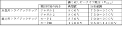
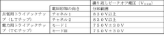
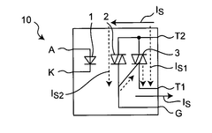
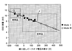
Solid state relay, power triac chip, and method for testing solid state relay
PatentWO2016194436A1
Innovation
- The design of the solid-state relay includes a power triac chip with reduced bidirectional repetitive peak-off voltage imbalance by setting the difference between mode I and mode III peak-off voltages within a predetermined tolerance range, ensuring the power triac chip's peak-off voltage is lower than the ignition triac chip's, and implementing a testing method to ensure products meet specific peak-off voltage standards for enhanced ESD resistance.
Calculating a load resistance
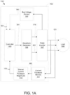
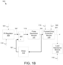
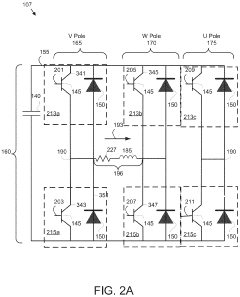
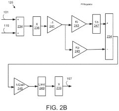
PatentActiveUS10527661B2
Innovation
- A system that includes a pulse width modulation (PWM) inverter with phase poles, a forward drop correction module, and a load resistance module, which calculates load resistance based on average control voltage, bus voltage, and load feedback current, correcting the control voltage using feedforward compensation to improve accuracy.
Safety Standards and Compliance Requirements
Testing solid-state relays (SSRs) in circuits requires strict adherence to established safety standards and compliance requirements to ensure operational safety and regulatory acceptance. The International Electrotechnical Commission (IEC) provides several key standards that govern SSR testing, including IEC 60947-4-3 for AC semiconductor controllers and IEC 62314 specifically for solid-state relays. These standards establish the minimum requirements for electrical isolation, temperature ratings, and load resistance testing methodologies.
In North America, Underwriters Laboratories (UL) standard UL 508 for industrial control equipment applies to solid-state relay testing, with particular emphasis on load resistance verification procedures. The standard mandates specific test conditions including ambient temperature ranges (typically 25°C ± 5°C) and humidity levels that must be maintained during resistance measurements to ensure consistent results.
European compliance is governed by the Low Voltage Directive (2014/35/EU) and Electromagnetic Compatibility Directive (2014/30/EU), which require comprehensive documentation of test procedures and results. When testing SSR load resistance, these directives necessitate the implementation of proper isolation measures between high and low voltage circuits, with minimum clearance distances specified based on working voltage levels.
Safety requirements for test equipment are equally stringent. IEC 61010-1 establishes safety requirements for electrical equipment used for measurement and testing, including insulation requirements, protection against electric shock, and mechanical hazards. Test instruments must be properly rated for the voltage category of the circuit being tested, typically CAT III or CAT IV for industrial applications involving SSRs.
Personal protective equipment (PPE) requirements must be observed during testing procedures. NFPA 70E in the United States and equivalent international standards specify appropriate PPE based on arc flash hazard analysis. For most SSR load resistance testing, this includes insulated tools, safety glasses, and insulating gloves rated for the appropriate voltage class.
Documentation requirements represent another critical compliance aspect. ISO 9001 quality management systems mandate detailed test records including calibration certificates for test equipment, environmental conditions during testing, and traceability of measurements. For industries like medical devices or automotive applications, additional standards such as ISO 13485 or ISO 26262 impose more rigorous documentation and validation requirements for SSR testing procedures.
Periodic calibration of test equipment is mandatory under most standards, with typical calibration intervals ranging from 6 to 12 months depending on usage frequency and environmental conditions. Test equipment must be traceable to national or international measurement standards, with calibration certificates maintained as part of the compliance documentation package.
Cost-Benefit Analysis of SSR Testing Solutions
When evaluating SSR testing solutions, cost-benefit analysis reveals significant variations across different methodologies. Traditional manual testing using multimeters typically requires minimal initial investment ($50-200 for quality equipment) but demands substantial labor hours, increasing operational costs over time. For organizations conducting frequent SSR testing, automated testing systems present compelling long-term economics despite higher upfront costs ($1,000-5,000), reducing testing time by approximately 70-80% and virtually eliminating human error.
The financial impact of testing method selection extends beyond equipment costs. Manual testing methods incur hidden expenses through increased downtime and potential measurement inconsistencies. Analysis of industrial implementation data indicates that automated systems typically achieve return on investment within 12-18 months for facilities performing weekly SSR testing, primarily through labor savings and improved accuracy.
Preventive maintenance economics strongly favor regular SSR load resistance testing. Field studies demonstrate that early detection of SSR degradation through systematic resistance monitoring reduces catastrophic failure rates by up to 65%. The average cost of emergency SSR replacement, including downtime and rush service, typically exceeds planned maintenance by a factor of 4-6, making proactive testing economically advantageous even when accounting for testing equipment depreciation.
For small-scale operations with limited SSR deployment, outsourced testing services present a balanced cost-benefit profile. Third-party testing services typically charge $75-150 per site visit, offering specialized equipment access without capital investment. However, this approach becomes less economical once a facility exceeds approximately 15-20 SSRs requiring regular monitoring.
Training requirements represent another significant cost consideration. Technical staff require approximately 4-8 hours of training for proficiency with advanced SSR testing equipment, representing a one-time investment of $200-400 per technician. This contrasts with the ongoing quality control challenges of manual testing, where measurement technique variations can persist despite training efforts.
Lifecycle analysis reveals that comprehensive SSR testing programs extend relay operational lifespan by 30-40% on average, primarily by enabling timely intervention before catastrophic failure. When factoring extended equipment life against testing program costs, organizations typically realize net positive returns within the second year of implementation, with increasingly favorable economics thereafter as prevention of emergency replacements compounds financial benefits.
Unlock deeper insights with Patsnap Eureka Quick Research — get a full tech report to explore trends and direct your research. Try now!
Generate Your Research Report Instantly with AI Agent
Supercharge your innovation with Patsnap Eureka AI Agent Platform!