

Stapler
A stapler and staple technology, applied in the direction of nailing U-shaped nail tools, nailing tools, manufacturing tools, etc., can solve the problem that the opening at the lower end cannot be opened and closed
- Summary
- Abstract
- Description
- Claims
- Application Information
AI Technical Summary
Problems solved by technology
Method used
Image

Examples
no. 1 example
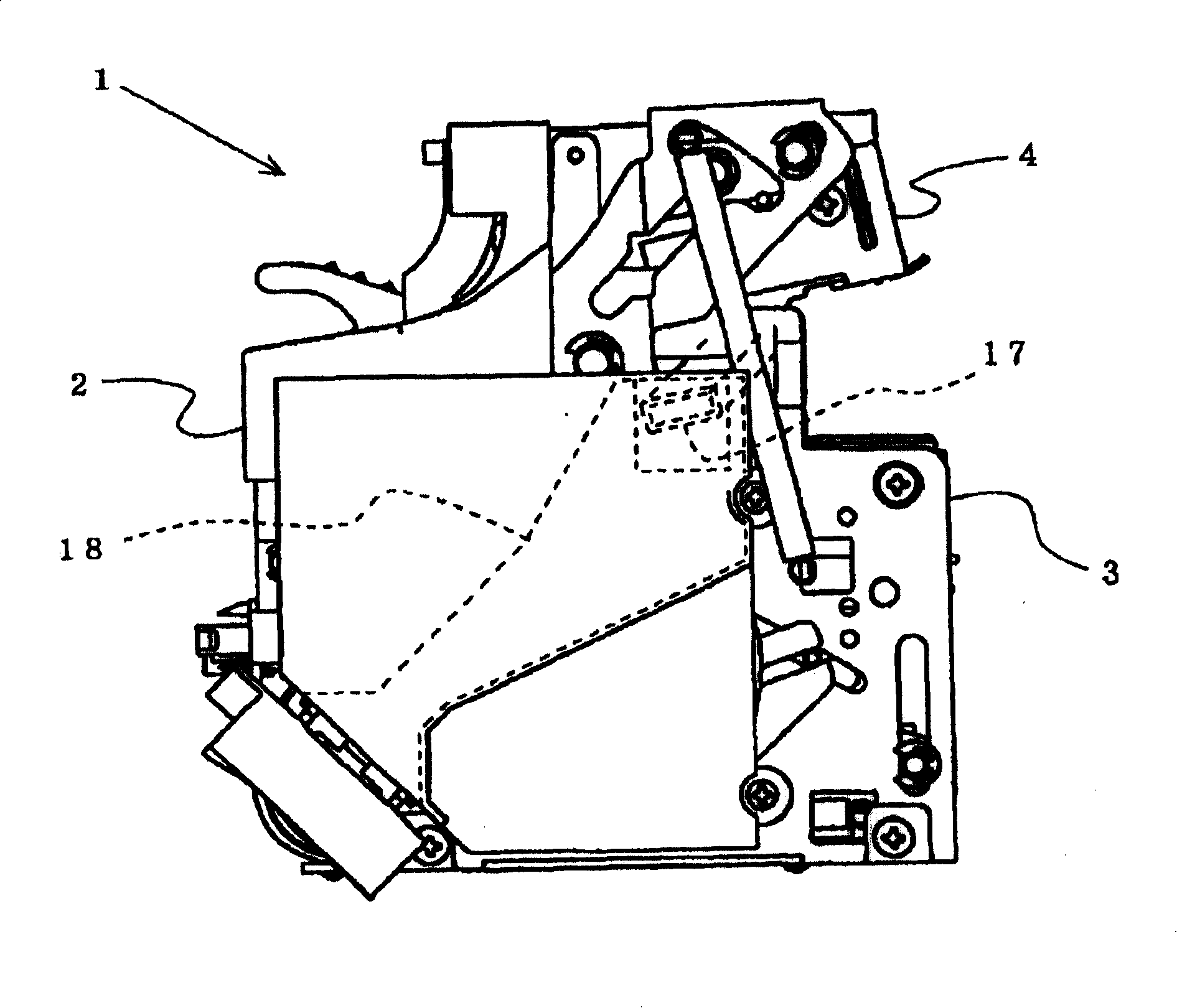
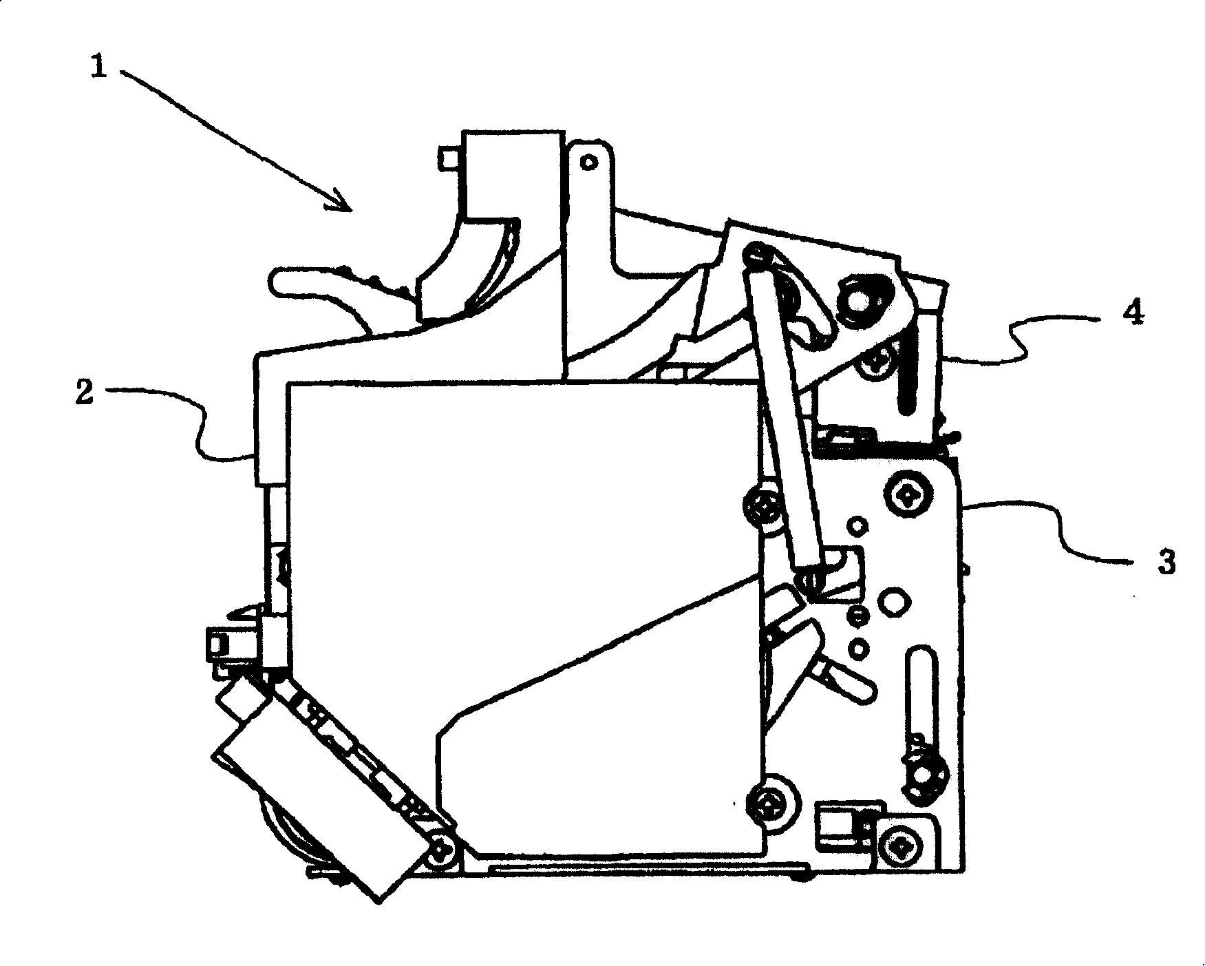
[0048] figure 1 It is a stapler that implements the cutting unit of the first embodiment of the present invention. A motor and a drive mechanism that is rotationally driven by the motor are accommodated in a machine frame 2 that forms the outline of the stapler 1. The lower part is formed with driving mechanism part 3, and this driving mechanism part 3 is driven by above-mentioned drive mechanism, will be formed into the U-shaped staple and drives out to binding paper. The driving mechanism part 3 of the stapler 1 of this embodiment is constituted as follows, a plurality of straight staple materials connected to each other are formed into U-shaped staples by a forming device, and simultaneously, the formed staples are formed by a driving device. The staple is driven upward toward the binding paper arranged above the driving mechanism unit 3 . In addition, a clamp mechanism part 4 is formed on the upper part of the machine frame 2 facing the driving mechanism part 3, and the c...
no. 2 example
[0063] Figure 14 It is a side view showing the stapler 101 implementing the staple cutting waste processing device according to the second embodiment of the present invention. In the machine frame 102 that forms the outer contour of this stapler 101, a motor and a driving mechanism driven by the motor are accommodated. In addition, a driving mechanism part 103 is formed at the bottom of the above-mentioned machine frame 102. 103 is driven by the above-mentioned driving mechanism, and the staples formed in a U-shape are driven out to the binding paper. The driving mechanism part 103 of the stapler 101 of this embodiment is constituted as follows, a plurality of straight staple materials connected to each other are sequentially supplied to the staple driving part of the driving mechanism part 103, The staple material of driving part is formed into the staple of U-shaped by forming device, simultaneously, by the driving device that is formed in above-mentioned staple, this form...
PUM
 Abstract
Description
Claims
Application Information