Air cleaner

An air filter and air technology, applied in the fields of dispersed particle filtration, chemical instruments and methods, dispersed particle separation, etc., can solve the problems of blockage of element mesh, easy pressure loss, inappropriate structure, etc., to increase the passage. The effect of small area and via resistance and large via area

Inactive Publication Date: 2009-04-08
KOMATSU LTD
View PDF9 Cites 0 Cited by
  • Summary
  • Abstract
  • Description
  • Claims
  • Application Information

AI Technical Summary

Problems solved by technology

[0010] Since both ends of the cylindrical element in the longitudinal direction are closed, air passes from the outer peripheral side of the element to the inner peripheral side, making it difficult to secure a sufficiently large air passage area.
However, there is a possibility that the pressure loss of the intake air becomes large, and when used for intake air of an engine, the performance may decrease.
Or, there is a problem that clogging of the mesh of the element is likely to occur, and the cleaning interval of the element is shortened.
[0011] In the above structure described in Document 2, the flow direction of the air is the axial direction of the element (direction along the tank chamber 97). Structurally unsuitable in case of horizontal discharge

Method used


Image

  • Air cleaner
  • Air cleaner
  • Air cleaner

Examples


no. 1 Embodiment approach

[0038]Next, a first embodiment of the present invention will be described with reference to the drawings. In addition, in the second embodiment and below, the same reference numerals are assigned to the same components and functions as those in the first embodiment described below, and descriptions of these components in the second embodiment and below are omitted or simplified.

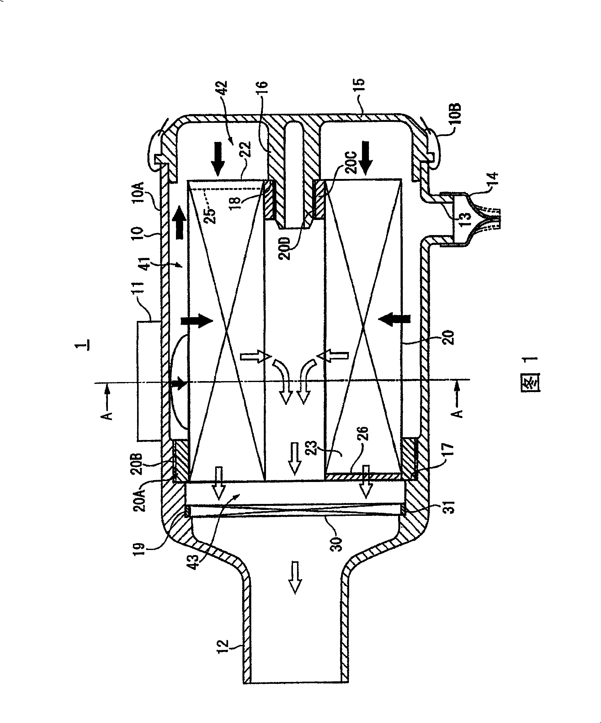
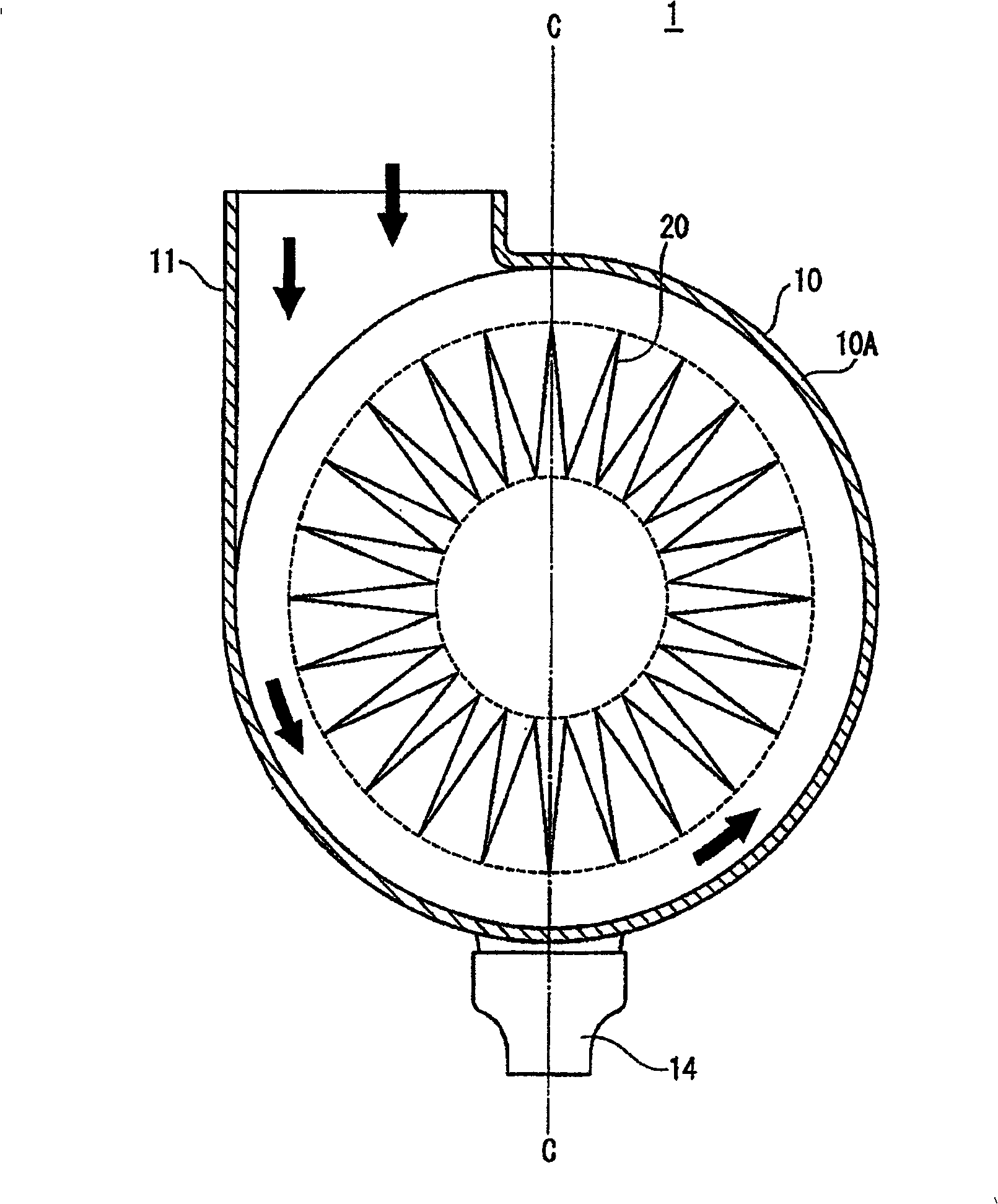
[0039] FIG. 1 shows a cross-sectional view of an air filter 1 according to a first embodiment. figure 2 It is the A-A line view of Fig. 1 .

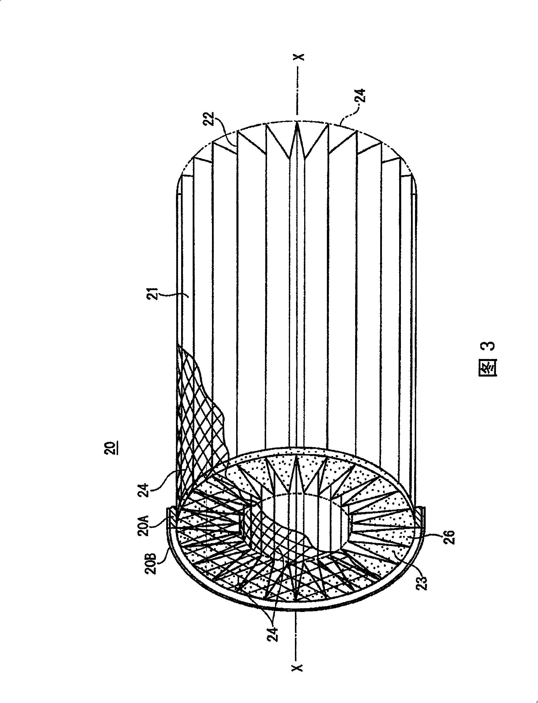
[0040] In Figure 1, figure 2 Among them, the air filter 1 is a device mounted on a construction machine that works on a sandy and dusty construction site, etc., and includes: a cylindrical casing 10 having a casing main body 10A that is open at one end; A filter element 20 inside; a safety filter (safety filter) 30 disposed on the downstream side of the filter element 20 in the same casing 10 .

[0041] The outer peripheral part of the casing 10, on the ...

no. 2 Embodiment approach

[0062] Fig. 7 is a cross-sectional view of an air filter 2 according to a second embodiment of the present invention. Figure 8 It is a sectional view taken along line VIII-VIII in FIG. 7 .

[0063] In Figure 7, Figure 8 In the air filter 2 shown in , in the inner peripheral side of the end portion on the casing 15 side of the casing main body 10A, a support portion 51 that supports the outer peripheral portion of the filter element 20 is provided. The outer peripheral side holding member 61 is bonded to the outer peripheral portion of the filter element 20 , and when the filter element 20 is stored in the cabinet 10 , the outer peripheral side holding member 61 abuts against the support portion 51 to hold one end of the filter element 20 . The end portion of the casing body 10A side of the casing 15 is provided with a butt joint 52, and when the casing 15 is installed in the casing body 10A, the butt joint 52 abuts with the side surface of the outer peripheral side holding ...

no. 3 Embodiment approach

[0066] In the air filter 3 of the third embodiment shown in FIG. 9 , the shapes of the casing 10 and the filter element 20 are largely different from those of the first and second embodiments.

[0067] That is, the casing main body 10A of the casing 10 in this embodiment is substantially box-shaped with an upper side open, and the air output duct 12 is provided on the lower side of the casing 10 . In addition, an air inlet pipe 11 is provided on the casing 15 to close the opening of the casing main body 10A.

[0068]Inside the casing 10, a housing portion 53 for housing the rectangular parallelepiped filter element 20 is provided. In the accommodating portion 53, set: the upper side opening 54 that is used to drop into the filter element 20 from above; the lower side opening 55 that the filtered air flows out from below; The opposite inlet-side opening portion 56 and the outlet-side opening portion 57 opposite to the open end portion of the peak portion 22 .

[0069] In addi...


PUM


Abstract

The present invention provides an air cleaner, in which a casing has an air inlet pipe making air inflow along a direction perpendicular to the axis of a cylindrical filter element, and an air outlet pipe making filtered air outflow along the axis, and the casing has a supporter clingingly supporting the end outer circumference of the filter element on closed valley portions side along the circumference direction continuously, and another supporter supporting the end inner circumference of the filter element on closed mountain portions side along the circumference direction continuously to close a hollow portion, and air to be filtered inflows to the filter element from a first inflow space on the top side of the mountain portions as well as from the end of a second inflow space side, and filtered air outflows from the end on an outflow space side as well as from the hollow portion.

Description

technical field [0001] The present invention relates to an air filter, and more particularly to an air filter for a vehicle engine used in a dusty place. Background technique [0002] In the past, regarding the structure of the air filter and the filter element used therein, for example, a 2-cartridge air filter has been described in the publication No. 59-133762 (hereinafter referred to as document 1) , Fig. 2, Fig. 3), and a serial air filter is described in JP-A-2000-508974 (hereinafter referred to as document 2) (also refer to page 12, Fig. 1 of this document). [0003] FIG. 14 is a side cross-sectional view of a two-cartridge air filter 70 described in Document 1. As shown in FIG. In FIG. 14 , a cylindrical casing (casing) 71 is equipped with an inlet pipe 72 on the side surface, an outlet pipe 73 is provided at the center of the blocking plate, and a bridge 74 having a pair of legs welded to the inner side of the outlet pipe 73 is provided. Extending along the open e...

Claims


Application Information

Patent Timeline
Patent Type & Authority Patents(China)
IPC IPC(8): B01D46/08
Inventor 西山利彦松嶋茂雄
Owner KOMATSU LTD
Why Eureka
Try Eureka