High pressure or middle pressure rotating connector and marine structure

A rotary joint, high voltage technology, applied in the direction of rotary collectors, connections, collectors, etc., can solve the problems of dielectric oil pollution, maximum voltage limit, limit maximum voltage, etc., to achieve high dielectric strength, pollution reduction, insulation The effect of property retention

Inactive Publication Date: 2009-10-14
SINGLE BUOY MOORINGS INC
View PDF3 Cites 0 Cited by
  • Summary
  • Abstract
  • Description
  • Claims
  • Application Information

AI Technical Summary

Problems solved by technology

[0003] The known rotary joints have the disadvantage that the dielectric oil can be contaminated by particles arising from the carbon brushes during wear
Accordingly, the maximum voltage that can be delivered by the rotary joint is limited
[0004] Furthermore, the use of flow-through dielectric insulators in the known rotary joints is relatively complex and requires an additional fluid-tight design of the pump and bearings, while at the same time limiting the maximum voltage transmitted by the rotary joints

Method used


Image

  • High pressure or middle pressure rotating connector and marine structure
  • High pressure or middle pressure rotating connector and marine structure
  • High pressure or middle pressure rotating connector and marine structure

Examples


Embodiment Construction

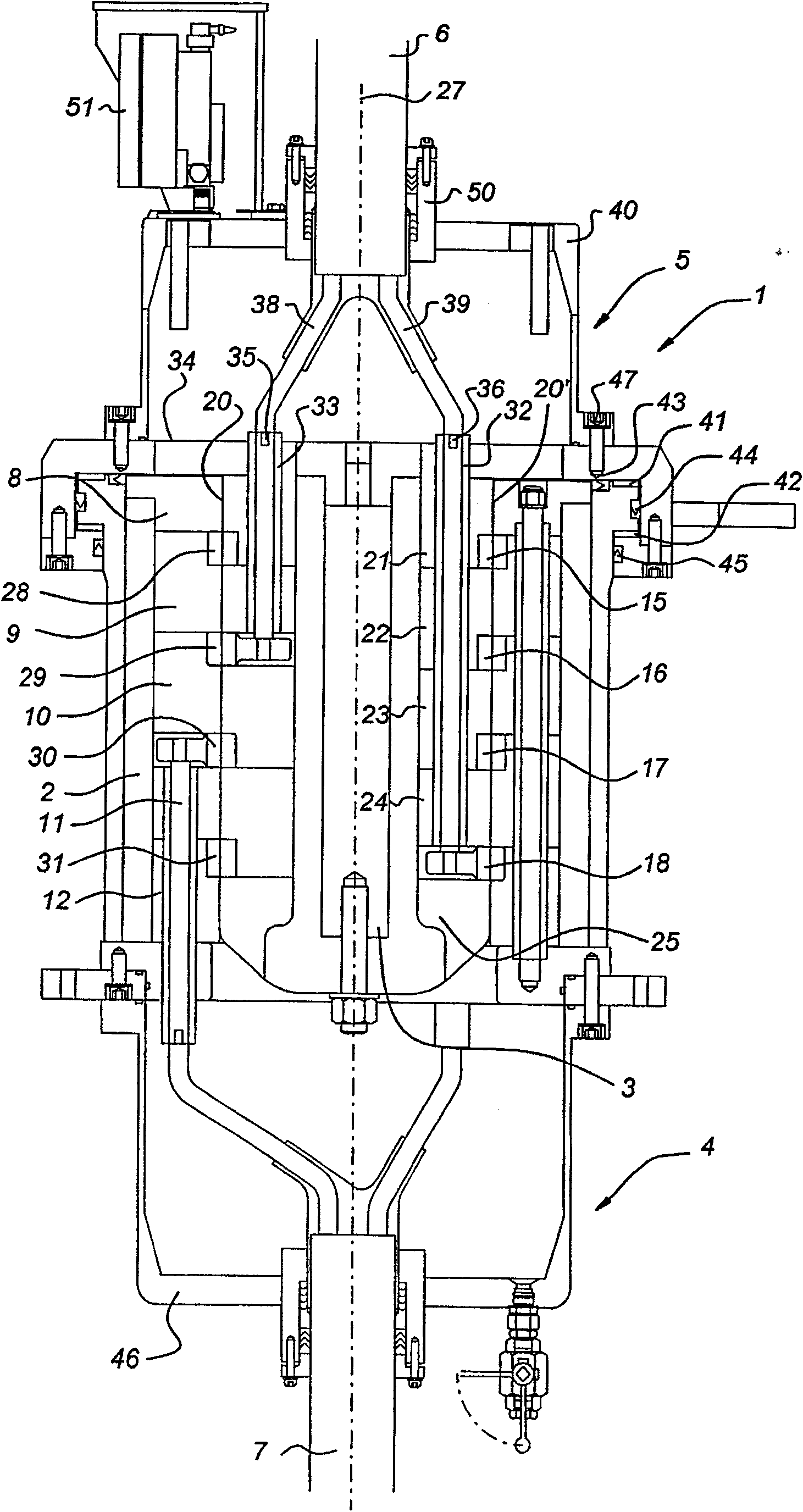
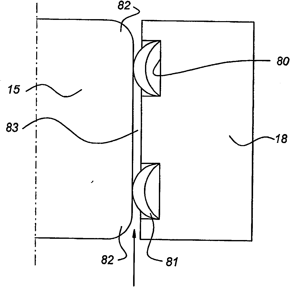
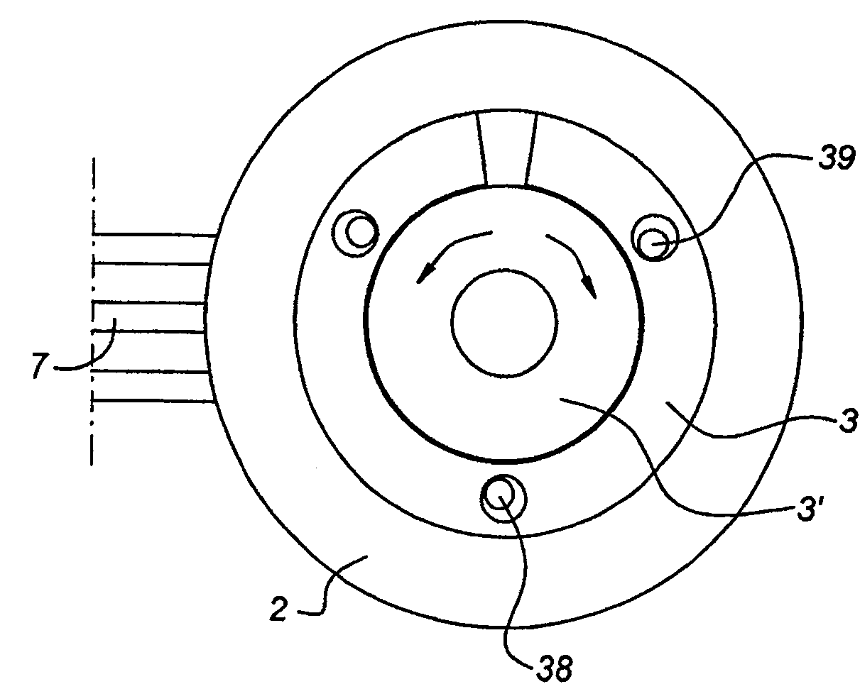
[0025] figure 1 Shown is a high pressure swivel 1 comprising a fixed outer annular wall 2 and an inner cylindrical support 3 . Said outer annular wall 2 is connected to top and bottom connector boxes 4, 5 for connecting three-phase cables 6, 7 respectively. Inside said annular wall 2 , five insulating rings 8 , 9 , 10 , 11 and 12 are arranged, which are fixed to the outer wall 2 . In each insulating ring 9 to 12, a recess is provided respectively, in which ring conductors 15, 16, 17, 18 are placed. The boundary surfaces of the outer insulating rings 8 to 11 are kept in contact with the boundary surfaces of the four inner annular insulators 21 to 24 fixed to the inner cylindrical element 3 . The inner annular insulators 21 to 24 and the cylindrical element 3 are rotatable about a longitudinal axis 27 . Conductors 28 to 31 are arranged in corresponding recesses of said respective insulating rings 21 to 24 . The respective conductors 28 to 31 are preferably formed from ring c...


PUM


Abstract

The present invention relates to a high pressure swivel comprising an annular outer element and an inner cylindrical element. The inboard and outboard elements each include at least two axially spaced electrical conductors rotatable with the respective inboard and outboard elements, the conductors forming at least two pairs positioned to have contact surfaces in electrical contact with each other. One conductor in each pair is provided on the inner element and the other on the outer element, and each conductor is connected to a respective voltage line extending to an input terminal and an output terminal respectively, the conductors being surrounded by insulating material. The electrical conductor of the outer element is arranged in a recess located in the outer insulating ring of the annular entity, and the electrical conductor of the inner element is arranged in a recess located in the inner insulating ring of the annular entity, the inner insulating ring is coaxial with the outer insulating ring, and the inner and outer insulating rings Axially extending boundary surfaces are respectively defined, the boundary surfaces of the rings are closely adjacent to each other, and the contact surfaces of the electrical conductors are located at or close to the boundary surfaces.

Description

technical field [0001] The present invention relates to a high pressure swivel comprising an annular outer member defining a cylindrical chamber around a longitudinal axis and an inner cylindrical member coaxial with said outer member and relative to said outer member about said longitudinal axis. The outer elements are rotatable, the inner and outer elements each comprise at least two axially spaced electrical conductors, the conductors are rotatable with the respective inner and outer elements, the conductors are at least two pairs arranged to have The contact surfaces are in electrical contact with each other, one conductor in each pair is provided on the inner member and the other conductor is located on the outer member, and the conductors are connected to the respective conductors extending to the input terminal and the output terminal. Corresponding to the voltage line, the conductor is surrounded by insulating material. The invention also relates to a medium pressure ...

Claims


Application Information

Patent Timeline
Patent Type & Authority Patents(China)
IPC IPC(8): H01R39/00H01R39/64
Inventor 斯图尔特·朗迈尔勒内·佩拉托内杰克·波拉克
Owner SINGLE BUOY MOORINGS INC
Why Eureka
Try Eureka