A protection device for the optical fiber line in the passive optical network and its method

A passive optical network and optical fiber line technology, applied in the direction of optical fiber transmission, electromagnetic wave transmission system, electrical components, etc., can solve the problems of inability to know the working status of the backbone optical fiber line, incompatibility with the backbone optical fiber, unpredictability, etc., to save operation. and maintenance costs, shorten the time of interruption of business, the effect of high user satisfaction

Active Publication Date: 2007-08-01
FENGHUO COMM SCI & TECH CO LTD
View PDF0 Cites 26 Cited by
  • Summary
  • Abstract
  • Description
  • Claims
  • Application Information

AI Technical Summary

Problems solved by technology

Full-fiber protection switching adopts two sets of independent OLTs and optical interfaces and optical fiber lines on the ONU side. In addition to meeting all the functions of backbone optical fiber protection, it can also realize the protection switching of the main and backup optical lines on the ONU side. Benefits It is more reliable, but the disadvantage is that the cost is high
The first method is to use an optical switch on the OLT side for switching. The disadvantage is that because only one optical module is used, when the system is working on the current backbone optical fiber line, the working status of the other backbone optical fiber line cannot be known. It will cause the system to be unpredictable about the consequences of the protection switching action to be taken, so it has the hidden danger of causing system instability. A typical example is that during the forced switching operation, it may be caused by another backbone optical fiber line itself. has been interrupted and forcibly switched to the past
Another way is to use two optical modules on the OLT side to correspond to the two backbone optical fiber lines respectively. An error occurred in the former method, but since this method adopts one of two methods to process the two upstream signals received on the main and standby optical fiber lines, it cannot be compatible with backbone optical fiber protection switching and all-fiber optical fiber protection switching in hardware. Protection switching, these two typical line protection methods, obviously have defects

Method used


Image

  • A protection device for the optical fiber line in the passive optical network and its method
  • A protection device for the optical fiber line in the passive optical network and its method
  • A protection device for the optical fiber line in the passive optical network and its method

Examples


Embodiment Construction

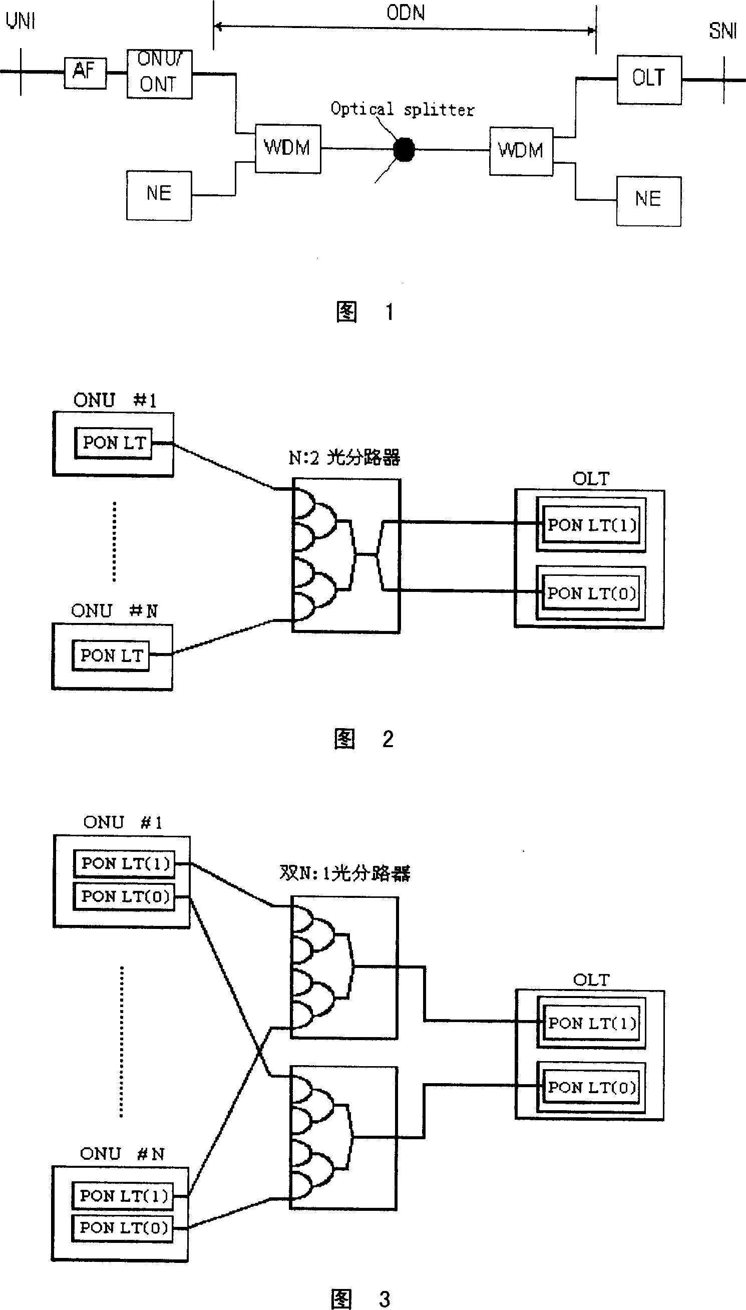
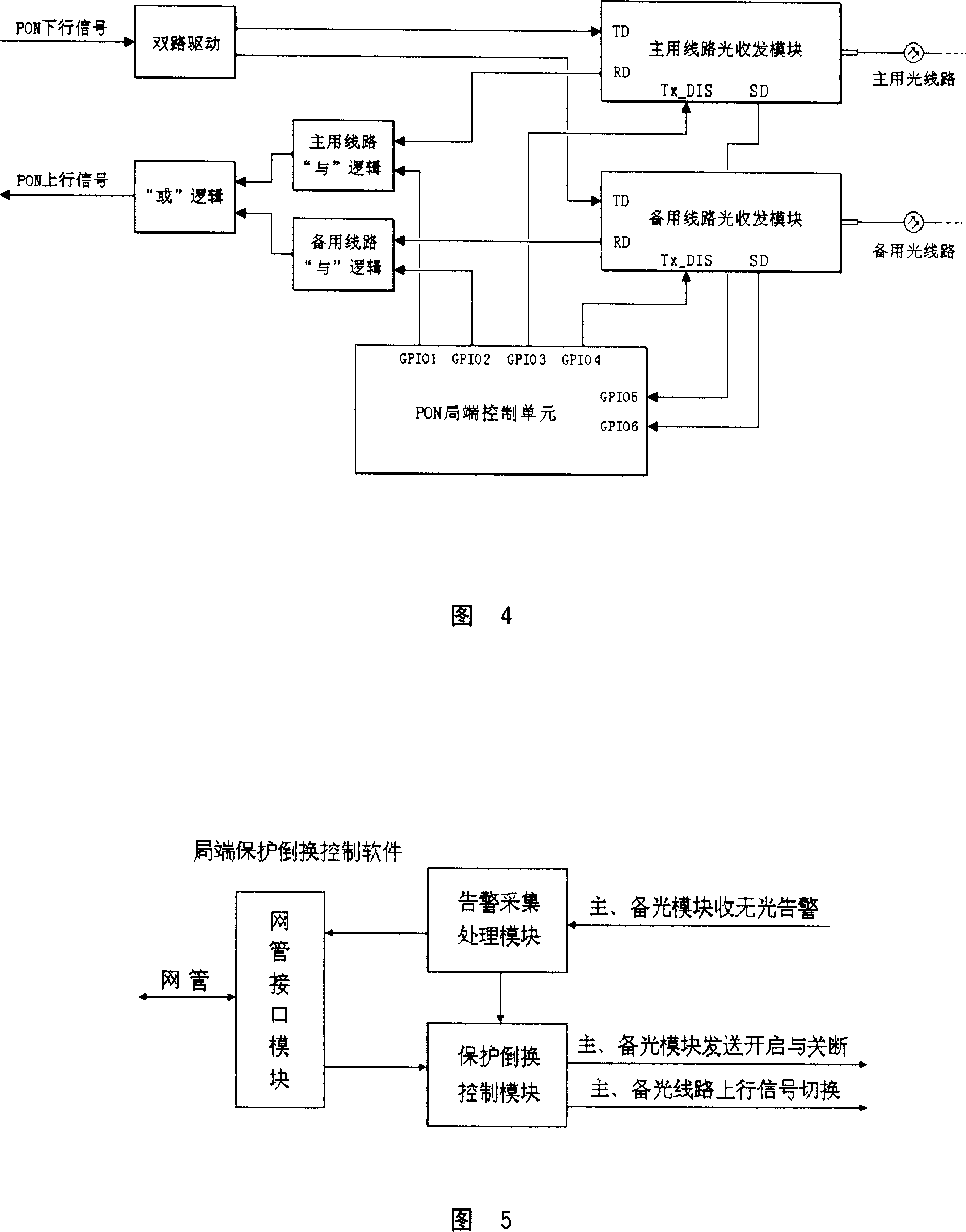
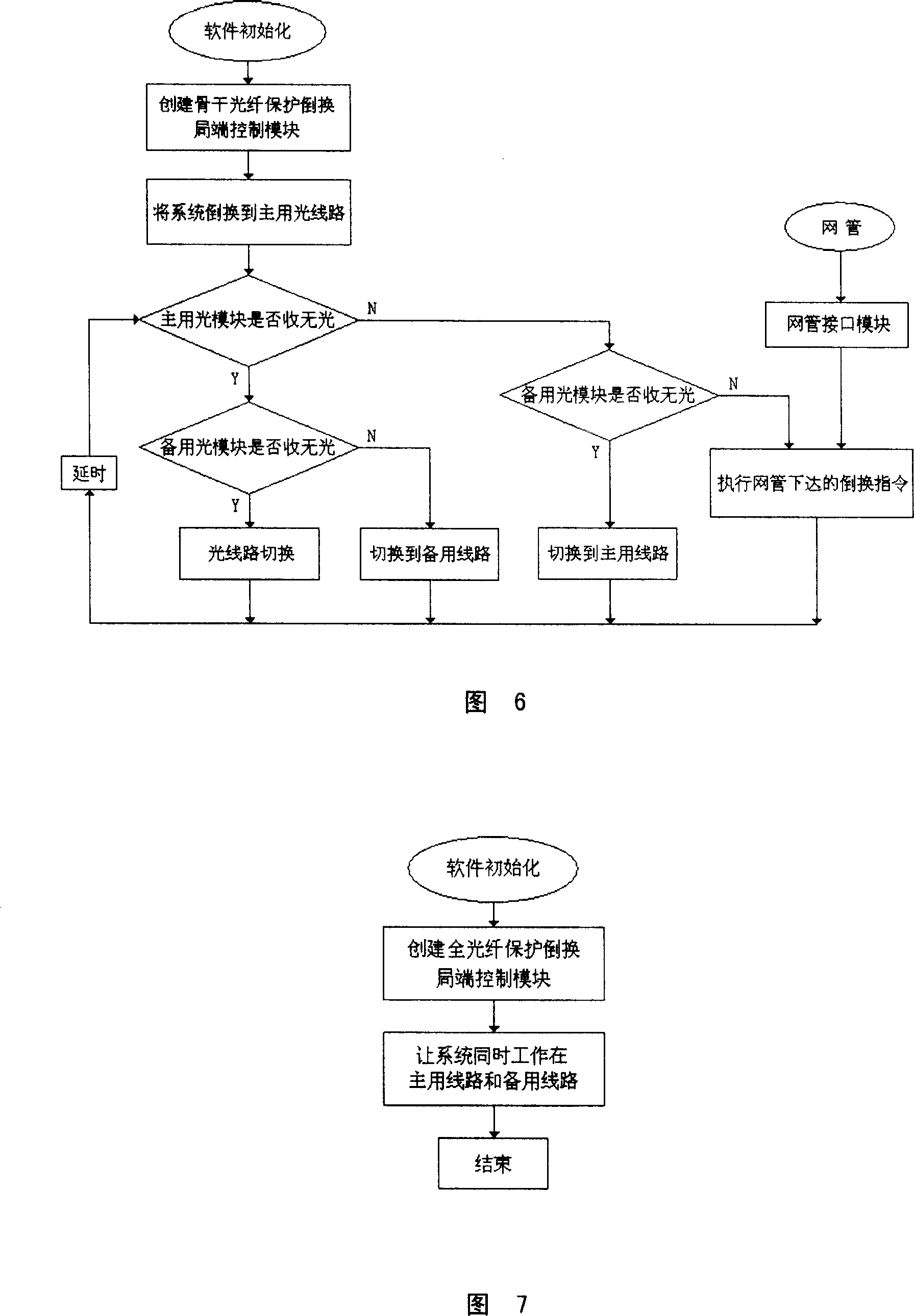
[0021] Aiming at the drawbacks of the two protection methods in the prior art, we propose a new method to protect optical fiber lines in the passive optical network (PON). The networking method is still as shown in Figure 2 and Figure 3 Show. In our method, two optical modules are used on the OLT side to correspond to the two backbone optical fiber lines, and the receiving and sending of the two optical signals can be turned on and off through control. When the system works in the backbone optical fiber protection switching mode, only one of the two optical modules sends downlink optical signals, and only one of the uplink optical signals received by the two optical modules can be selected to pass; when the system works in full-fiber protection switching In this mode, two optical modules send downlink optical signals at the same time, and the uplink optical signals received by the two optical modules are also selected to pass through at the same time. After being operated by a...


PUM


Abstract

The invention provides a device and method that realizes the protection of fiber line in PON. It adopt two light modules to correspond two skeleton fiber lines in local end OLT, the receiving and sending of two light signals can be started and closed by controlling. When system is working in skeleton fiber protection rearranging mode, only one module of the two sends down light signal, only one of two upper light signals can be selected to pass; when system is working in full fiber protection rearranging mode, two light modules can send down light signal at the same time, and the upper light signals can be selected to pass. Based on the invention, long time interruption can not be happened, maintainer can appoint engineer repair the faulted light line without interrupting the operation.

Description

technical field [0001] The invention relates to the field of optical fiber communication, in particular to a device and method for protecting optical fiber lines in a passive optical network (PON). Background technique [0002] After several years of development, from the early non-standard narrowband PON and standard APON and BPON, to the IEEE-standardized EPON based on Ethernet technology and the GFP-based ITU-T standardized GPON and PON technology in the past two years It has gone through a process of gradual improvement and perfection. As the most ideal FTTH broadband access method at present, PON technology entrusts the ideal in the hearts of optical communication workers. Whether it is EPON or GPON, they all have the same network topology. How to make them work efficiently and reliably in the communication network is a problem that we must often think about. [0003] PON consists of an optical line terminal (OLT) at the central office and several optical network uni...

Claims


Application Information

Patent Timeline
Patent Type & Authority Applications(China)
IPC IPC(8): H04B10/12H04B1/74H04B10/08H04B10/14H04B10/038H04B10/25
Inventor 曹桦侯景元何岩向东杨柳沈羽纶汪骏飞叶立生
Owner FENGHUO COMM SCI & TECH CO LTD
Why Eureka
Try Eureka