Fuel cell vehicle and vehicle

A technology for fuel cell vehicles and fuel cell systems, which is applied in the fields of fuel cells, fuel cell additives, and transportation fuel cell technologies, and can solve the problems of not paying attention to the existence of electric vehicles.

Inactive Publication Date: 2007-08-15
TOYOTA JIDOSHA KK
View PDF2 Cites 5 Cited by
  • Summary
  • Abstract
  • Description
  • Claims
  • Application Information

AI Technical Summary

Problems solved by technology

Therefore, even when an electric vehicle traveling at a low speed approaches a pedestrian, etc., sometimes the pedestrian does not notice the presence of the electric vehicle.

Method used


Image

  • Fuel cell vehicle and vehicle
  • Fuel cell vehicle and vehicle
  • Fuel cell vehicle and vehicle

Examples


no. 1 Embodiment approach

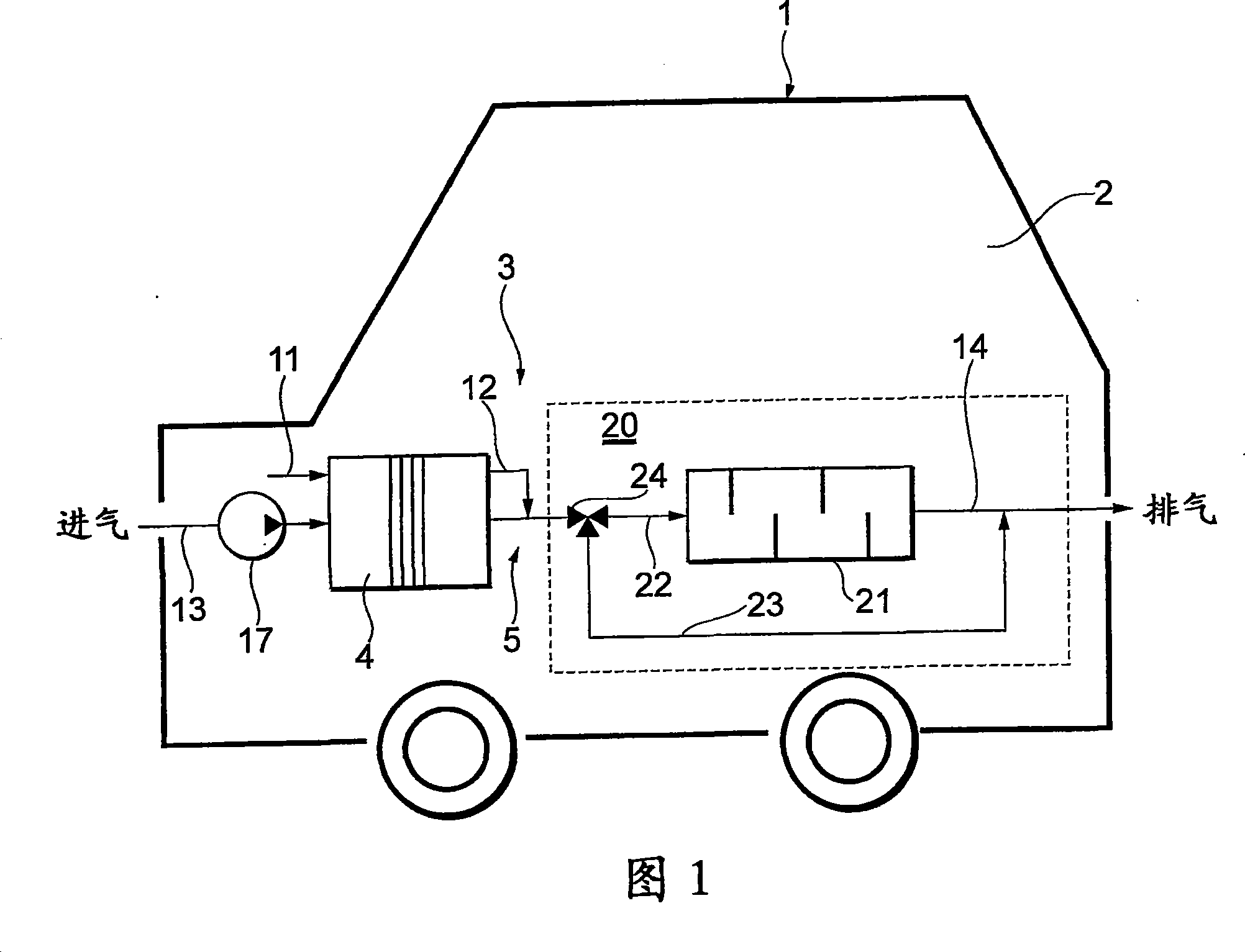
[0067] As shown in FIG. 1 , a fuel cell vehicle 1 is equipped with a fuel cell system 3 on a vehicle body 2 . The fuel cell 4 of the fuel cell system 3 is connected to an unillustrated drive motor via an unillustrated inverter, and the unillustrated drive motor rotates an unillustrated axle. Such a fuel cell vehicle is not limited to the four-wheeled fuel cell vehicle 1 shown in FIG. 1 , but may also be a two-wheeled vehicle, or may be an electric train, a bicycle, or the like.

[0068] The fuel cell 4 has a stack structure in which a plurality of single cells (single cells) are stacked. The fuel cell 4 generates electric power (driving energy) by receiving air as an oxidizing gas and hydrogen as a fuel gas. As the fuel cell 4, there are various types such as phosphoric acid type, but here it is composed of a solid polymer electrolyte type. As a method of supplying hydrogen to the fuel cell 4, a method of converting raw fuel such as natural gas into hydrogen on the vehicle b...

no. 2 Embodiment approach

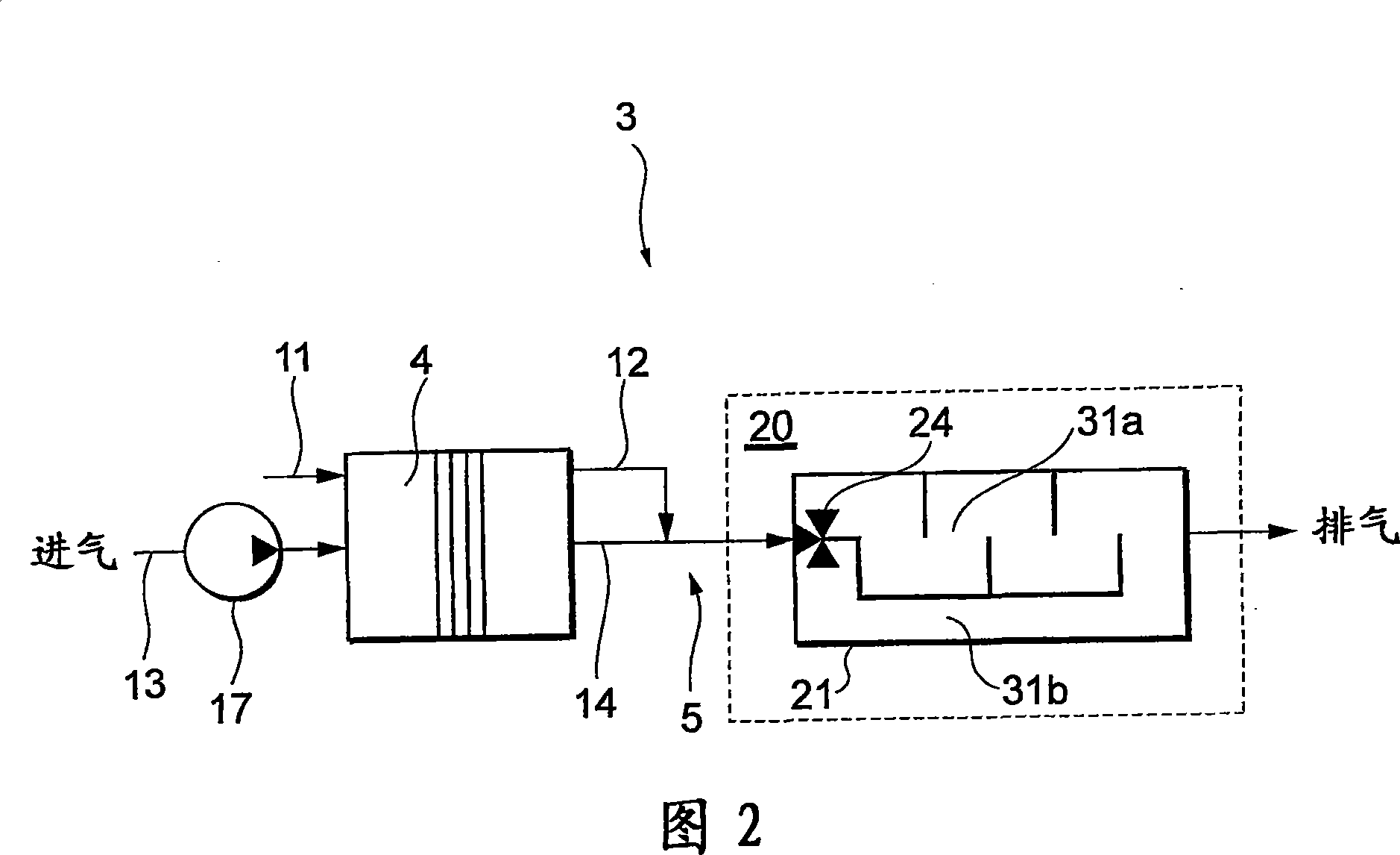
[0086] Next, referring to FIG. 2 , a fuel cell vehicle 1 according to a second embodiment will be described focusing on differences from the first embodiment. FIG. 2 shows a fuel cell system 3 mounted on a fuel cell vehicle 1 . The difference from the first embodiment is the structure of the muffler 20 .

[0087] The muffler 20 includes a muffler 21 that introduces the mixed gas in the oxidizing gas discharge line 14 to muffle the noise. The inside of the muffler 21 is divided into two silencing spaces 31a and 31b having different silencing capabilities. On the gas inlet side inside the muffler 21, a directional control valve 24 for switching between the two muffler spaces 31a, 31b is provided as a passage for introducing the mixed gas. The directional control valve 24 has the same structure as that of the first embodiment. The directional control valve 24 is mechanically operated based on the running condition of the fuel cell vehicle 1, and is switched to either of the tw...

no. 3 Embodiment approach

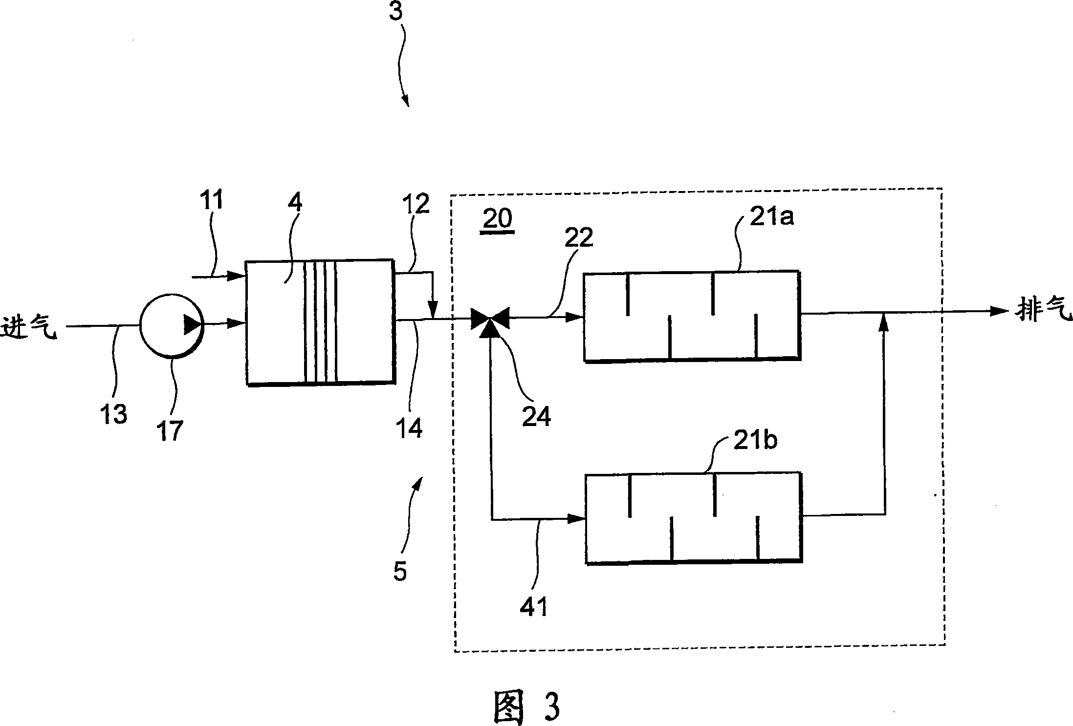
[0095] Next, a fuel cell vehicle 1 according to a third embodiment will be described focusing on differences from the first embodiment with reference to FIG. 3 . FIG. 3 shows a fuel cell system 3 mounted on a fuel cell vehicle 1 . The difference from the first embodiment is the structure of the muffler 20 .

[0096] The muffler unit 20 includes two mufflers 21a, 21b that introduce the mixed gas of the oxidizing gas discharge line 14 to muffle the noise, and a directional control valve 24 that switches to either of the two mufflers 21a, 21b.

[0097] One muffler 21 a is provided in the main airflow passage 22 , and the other muffler 21 b is provided in a branch passage 41 provided in parallel with the main airflow passage 22 . The upstream end of the branch passage 41 is connected to the directional control valve 24 , and the downstream end thereof is connected to the downstream side of the muffler 21 a of the main flow passage 22 . The directional control valve 24 is mechani...


PUM


Abstract

A fuel cell vehicle capable of producing a less unnatural traveling sound that is according to traveling conditions, and such a fuel cell vehicle is realized by making effective use of the fact that a sound muffling section is installed in gas piping of a fuel cell system. A fuel cell vehicle (1) mounted with a fuel cell system (3) having a sound muffling section (20) in gas piping (5), wherein muffling ability of the sound muffling section (20) is variable according to traveling conditions of the fuel cell vehicle (1). The muffling ability of the sound muffling section (20) lowers in low speed traveling. For example, the sound muffling section (20) has a directional control valve (24) that switches a flow path for a mixture gas to either a muffler (21) or a bypass path (23) according to traveling conditions. The directional control valve (24) may be mechanically operated by a gas flow speed or may be controlled for its switching operation by a control device (51).

Description

technical field [0001] The present invention relates to a fuel cell vehicle and a vehicle with quiet running sound. Background technique [0002] The running sound of an electric vehicle typified by an electric vehicle is lower than that of an engine vehicle equipped with an internal combustion engine. Therefore, even when an electric vehicle traveling at a low speed approaches a pedestrian or the like, the pedestrian or the like may not notice the presence of the electric vehicle. Therefore, for safety considerations, it has been proposed to install an analog sound generating device that produces an engine analog sound on the electric vehicle, and generate a scheme (for example, referring to patent document 1 and 2). [0003] Patent Document 1: Japanese Unexamined Patent Application Publication No. 2001-282263 (page 3 and drawing 1) [0004] Patent Document 2: JP-A-7-32948 (FIG. 1) Contents of the invention [0005] According to such a conventional electric vehicle, i...

Claims


Application Information

Patent Timeline
Patent Type & Authority Applications(China)
IPC IPC(8): B60L11/18H01M8/00B60K1/04H01M8/04B60K8/00H01M8/06B60K13/04H01M8/10
CPCY02T90/34B60R13/08H01M2250/20Y02T90/32G10K15/04H01M8/0662H01M8/04089B60K13/04Y02E60/50B60R13/0884B60L11/1881B60L2200/26B60L58/30Y02T90/40H01M8/04
Inventor 麻生真司
Owner TOYOTA JIDOSHA KK
Why Eureka
Try Eureka