Distributing transformator electronic type loaded automatic wide region voltage regulating device

A technology for distribution transformers and voltage regulating devices, which is applied to the parts of transformers/inductors, transformers, variable transformers, etc., and can solve the problem of failure to switch or control elements, separation of devices, imperfect protection functions, and short battery discharge time and other problems, to achieve the effect of improving the low voltage qualification rate and the difficulty of voltage regulation

Active Publication Date: 2010-11-17
李春光
View PDF2 Cites 0 Cited by
  • Summary
  • Abstract
  • Description
  • Claims
  • Application Information

AI Technical Summary

Problems solved by technology

However, if it is to be used as a "non-contact on-load automatic voltage regulation distribution transformer" that can be connected to the power grid for safe, economical and reliable operation, there are at least the following main problems: 1. Voltage fluctuation rate Exceeding the standard: the voltage regulation index of the three no-load taps of the ordinary transformer is ±5%U N , while my country's voltage fluctuation rate for 10KV power grids is ≦2.5%U N , so, this direct use of ±5%U N The voltage regulation tap is used for on-load voltage regulation, and it cannot reach the voltage fluctuation rate specified as ≦2.5%U N index requirements
[0004] 2. The voltage regulation wiring method of the common star point makes the withstand voltage problem of the solid state relay with a rated voltage of only a few hundred volts unable to be effectively solved in the high voltage winding, so that the voltage regulation range is limited; in addition, the traditional transition current limiting resistor is used This method not only increases the power loss of the transformer, but also increases the number, volume and cost of the N-1 group of current-limiting resistors and SSRs when the voltage regulation range exceeds the third gear. Rapid increase, it is difficult to install in the limited installation space
Therefore, these unfavorable factors cannot meet the practical requirements of increasing the voltage regulation level of the transformer.
[0005] 3. Safety issues: The control system shares a circuit board, which fails to effectively separate the switches or control components and devices in the high and low voltage areas, and shares a DC power supply (taken from the low voltage side of the transformer)
In this way, when the power grid is overvoltage or the transformer sends power phase by phase, if the switching elements and control leads placed in the high voltage winding are broken down by the high voltage, it will cause an accident that the 10KV high voltage will enter the 400V side (although there is a photoelectric isolation, but the withstand voltage is very limited), directly endangering the safety of low-voltage side equipment, electrical appliances and consumers
[0006] 4. Imperfect protection function: The operating environment of distribution transformers is poor. In actual power grid operation, the external failure rate is very high, such as: phase loss, overcurrent, short circuit, overvoltage, undervoltage grounding and other faults When any fault occurs, it will endanger the normal operation of the device, or even damage the equipment, causing a large-scale power outage, and these necessary protection measures are not introduced in its documents
We know that the installation and operating environment of distribution transformers is poor. Generally, few people stay on duty, especially in the large number of rural power distribution substation areas. Farm electricians sometimes go out for several days because they are busy with other work or go out for business. If you don’t go to the power distribution room, what should you do if you forget or fail to operate the switch in time when a sudden call comes in after a long power outage? The discharge time of the old battery will be shorter
Furthermore, the storage battery is installed in insulating oil. Once there is a problem with the seal, a large amount of electrolyte will also pollute the insulating oil, and even cause accidents in serious cases.
[0008] In short, if the above major problems cannot be effectively solved, then this technical solution is obviously not practical whether it is a new type of transformer or as a set of on-load automatic voltage regulation device.

Method used


Image

  • Distributing transformator electronic type loaded automatic wide region voltage regulating device
  • Distributing transformator electronic type loaded automatic wide region voltage regulating device
  • Distributing transformator electronic type loaded automatic wide region voltage regulating device

Examples


Embodiment 1

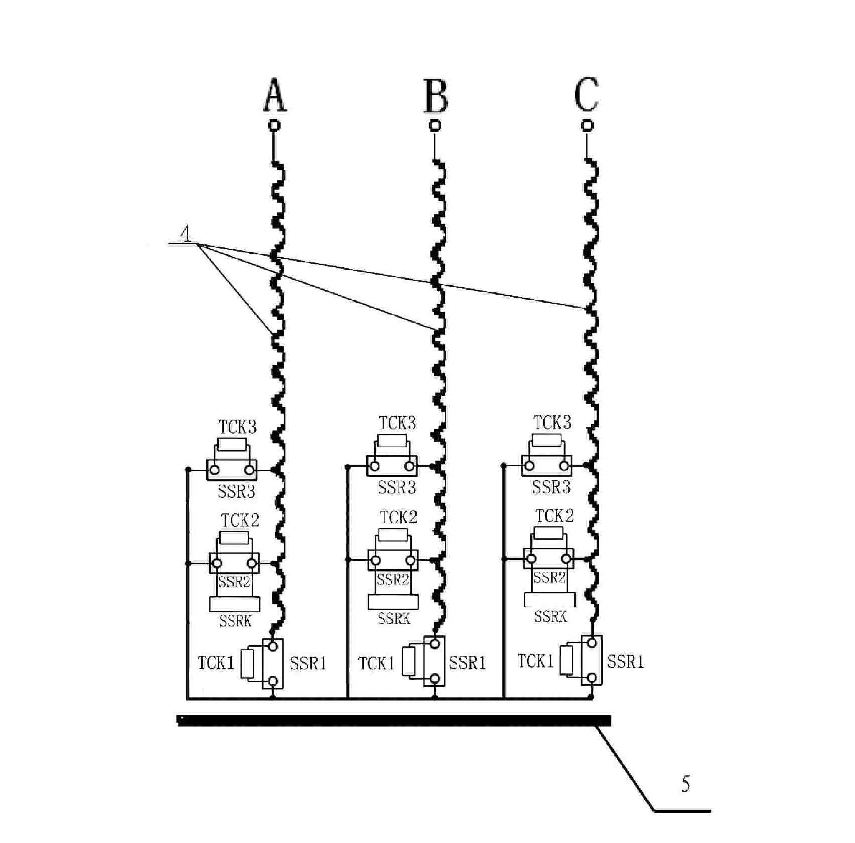
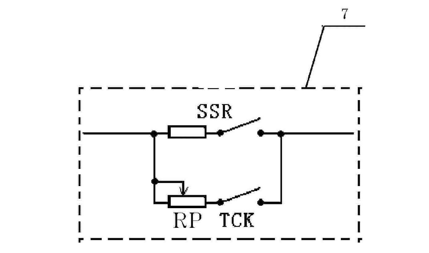
[0069] Refer to figure 1 , each dual-relay main control switch (SSR and TCK connected in parallel) is connected to the tap (7) on the corresponding level of the high-voltage side winding of the transformer, and the other end is connected in parallel as a star point. The voltage regulation level of the transformer is three levels or other odd-numbered levels are selected, and three second-level single-phase AC solid-state relays (SSR2 ) are respectively connected in parallel with a normally closed solid-state relay (SSRK) as a gatekeeper switch to form a gatekeeper control unit. The execution of the gatekeeper control unit is controlled by the gatekeeper control circuit. The single-phase AC solid-state relays connected to the command generator and the taps of other voltage-regulating stages are conventional normally open. The wiring scheme for voltage regulation above three gears is designed with reference to the first embodiment.

Embodiment 2

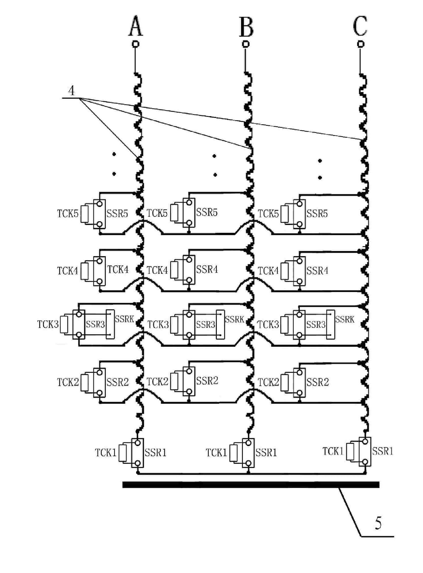
[0070] Refer to figure 2 , the other ends of the five double-relay main control switches (7) on the taps of the same voltage regulation level taps of the three-phase wires (4) of the high-voltage side winding of the transformer are connected in parallel. The voltage regulation level of the transformer is five levels or other odd-numbered levels are selected, and three three-level single-phase AC solid-state relays (SSR3) are connected in parallel on the tap taps of the middle voltage regulation level (that is, the third level) of the high-voltage winding of the transformer. A normally closed solid-state relay (SSRK) acts as a gatekeeper switch to form a gatekeeper control unit. The execution of the gatekeeper control unit is controlled by the gatekeeper control loop. Its upper stage and the three-phase quasi-command generator The single-phase AC solid-state relays connected with taps of other voltage-regulating grades are conventional normally open types. The wiring scheme f...


PUM


Abstract

The present invention relates to a power distribution electric-type load broad-range voltage adjusting device. The voltage regulating grades shunting taps of the transformer three-phase winding are respectively connected with a main control switch and a control system. The main control switch is a dual-relay main control switch formed by the in-series connection of a single-phase alternating current solid state relay SSR and a one-way magnetic protection relay TCK. Moreover, the voltage regulating grades shunting taps of the transformer three-phase winding are connected separately with one end of each main control switches. The other end of the main control switch is connected with the start point of the high-voltage side winding or with the start points of each-phase main control switches that regulate the voltage of the same grade; the intermediate voltage regulating shunting taps of the transformer high-voltage winding and the single-phase alternating current solid state relay are connected in parallel with a closed solid state relay as a watchdog stake switch. The device has the advantages of small body, simple structure, agile action, no impact of gear shifts, no circular current, no harmonious wave, low loss, good security, high reliability, low price, long service life and being free from operation and maintenance; and realizes the function of no circular current load voltage adjustment.

Description

technical field [0001] The invention relates to an on-load automatic voltage regulating device for a transformer, in particular to an on-load automatic voltage regulating device for a power distribution transformer in a power system. Background technique [0002] In order to ensure the quality of the power supply voltage, improve the reliability of power supply, and reduce the loss of the power grid, people have been using the mechanical on-load voltage regulating device of the transformer for many years. However, the mechanical on-load voltage regulation device is prohibitive for most small-capacity transformers due to its high price, large volume, and large operation and maintenance, especially the on-load voltage regulation rate of a large number of 10KV distribution transformers. It is almost zero. It can also be said that low-voltage distribution transformers are still blank in terms of on-load voltage regulation. With the development of society and economy, in the fac...

Claims


Application Information

Patent Timeline
Patent Type & Authority Patents(China)
IPC IPC(8): H01F27/04G05F1/14H01F29/02
Inventor 李春光
Owner 李春光
Why Eureka
Try Eureka