Electronic control method for choker and electronic control choker device

A technology of electronic control and electronic control unit, which is applied in the direction of control device, non-electric variable control, control/regulation system, etc. It can solve the problems of non-following, engine speed drop, engine flameout, etc., so as to avoid engine flameout and maintain the running state Effect

Inactive Publication Date: 2008-02-13
NIKKI CO LTD
View PDF1 Cites 2 Cited by
  • Summary
  • Abstract
  • Description
  • Claims
  • Application Information

AI Technical Summary

Problems solved by technology

[0004] However, there is a problem that when the load changes rapidly while the engine is running, or when the vehicle is driven without operating the accelerator, it often does not follow the control of the electronic control unit 10B, or there is a discrepancy between the predicted value and the actual value during the control. If there is a difference, the engine speed will drop sharply and the engine will stall

Method used


Image

  • Electronic control method for choker and electronic control choker device
  • Electronic control method for choker and electronic control choker device

Examples


Embodiment Construction

[0025] Hereinafter, specific embodiments for carrying out the present invention will be described with reference to the drawings.

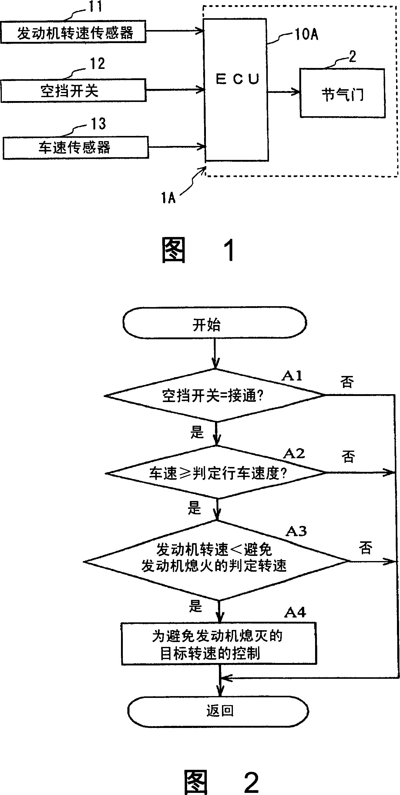
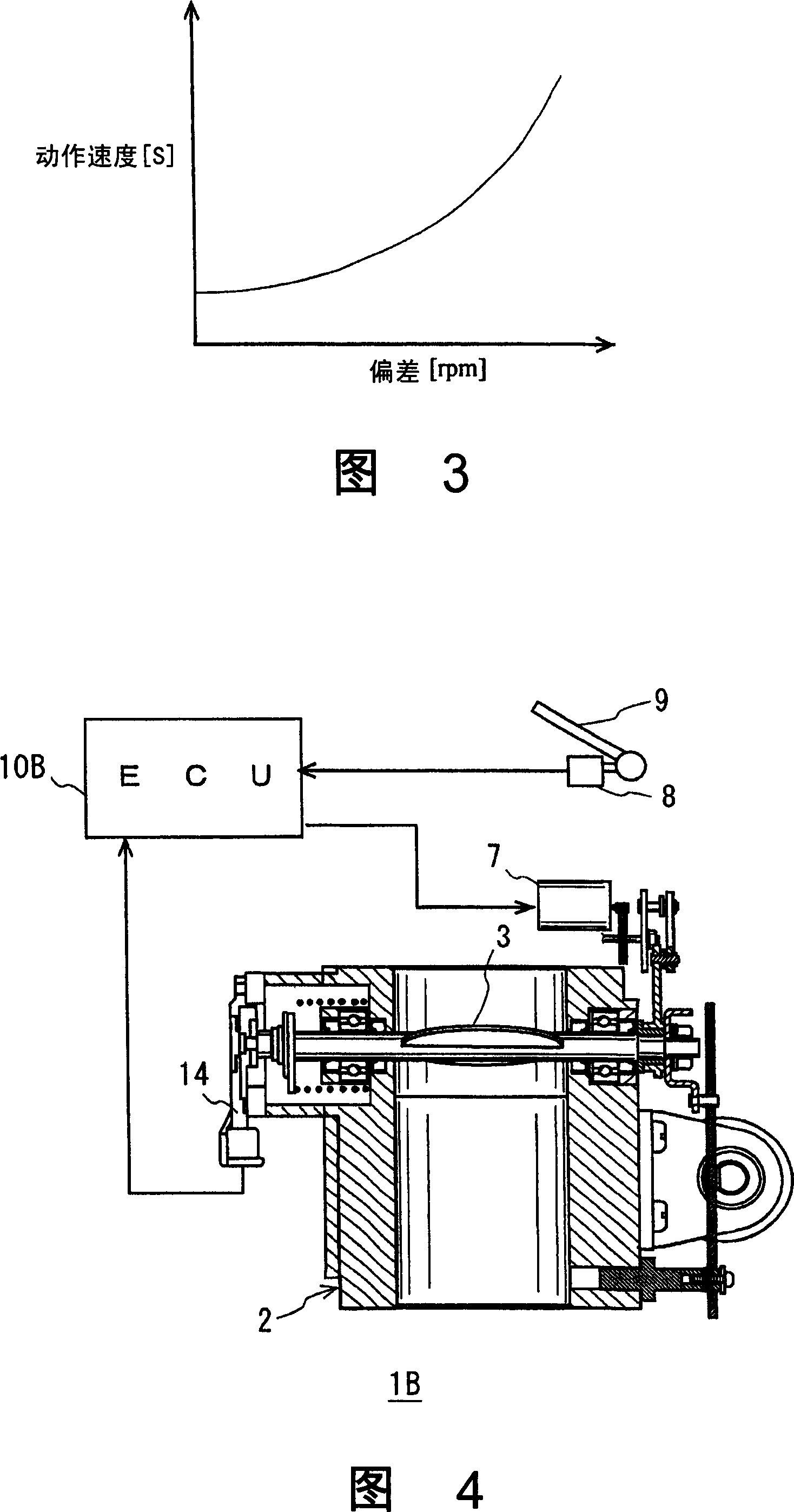
[0026] The hardware structure of the electronically controlled throttle device of the present embodiment is basically the same as that of the conventional device shown in FIG. Executor 7; and based on the accelerator opening data output from the accelerator opening sensor 8 attached to the accelerator 9 and the throttle opening data according to the throttle opening sensor 14, the required drive signal is sent to the actuator 7 The electronic control unit 10B, in particular, as shown in the schematic configuration diagram of FIG. 1, the electronic control unit 10A and the engine speed sensor 11 provided on the electronically controlled throttle device 1A, in order to detect whether the transmission The neutral switch 12 and the vehicle speed sensor 13 are connected.

[0027] In addition, although the electronic control device 10A mainly executes ...


PUM


Abstract

The engine system arranged with electronic control air throttle device can well maintain the running state of the engine as the system can reliably avoid the engine stall which is generated by the rotating speed descending of the engine. In the air throttle electronic control method which is executed by the electronic control air throttle device 1A to do on-and-off controlling to the air throttle 3 by the actuator 7 according to the instruction of the electronic control unit 10A, the electronic control unit 10A detects the output signal of the neutral position switch, the signal of the engine speed sensor, and the signal of vehicle speed sensor, when the speed changing box is at the stage changing position and the gear is at the connecting condition, besides, the vehicle speed is above the scheduled determinant rotary speed and the engine speed is below the scheduled determinant rotary speed when the engine stall is likely to happen, the system does controlling to the air throttle to hold the engine speed above the target rotary speed which is specified to avoid the engine stall.

Description

technical field [0001] The present invention relates to an electronic control method of a throttle valve and an electronic control throttle device. The electronic control method and the electronic control throttle device use an electronic control system to make a throttle valve installed in an intake system of a vehicle engine perform switching operations. In particular, it relates to an electronic control method of a throttle valve and an electronically controlled throttle valve device for avoiding engine stall caused by an excessive drop in engine speed when the engine is running. Background technique [0002] Recently, for example, as described in JP-A-5-240073, for the purpose of reducing vehicle fuel consumption and improving driving performance, in order to control the engine with high precision, the use of electronic control systems and electronic control systems have become popular. The electronically controlled throttle device with switching action replaces the mech...

Claims


Application Information

Patent Timeline
Patent Type & Authority Applications(China)
IPC IPC(8): F02D11/10B60K31/04
CPCY02T10/40
Inventor 柳川透
Owner NIKKI CO LTD
Why Eureka
Try Eureka