Refrigerating unit

A refrigeration device, refrigeration cycle technology, used in refrigerators, refrigeration components, refrigeration and liquefaction and other directions

Inactive Publication Date: 2008-06-11
DAIKIN IND LTD
View PDF1 Cites 8 Cited by
  • Summary
  • Abstract
  • Description
  • Claims
  • Application Information

AI Technical Summary

Problems solved by technology

solve th

Method used


Image

  • Refrigerating unit
  • Refrigerating unit
  • Refrigerating unit

Examples


no. 1 example 》

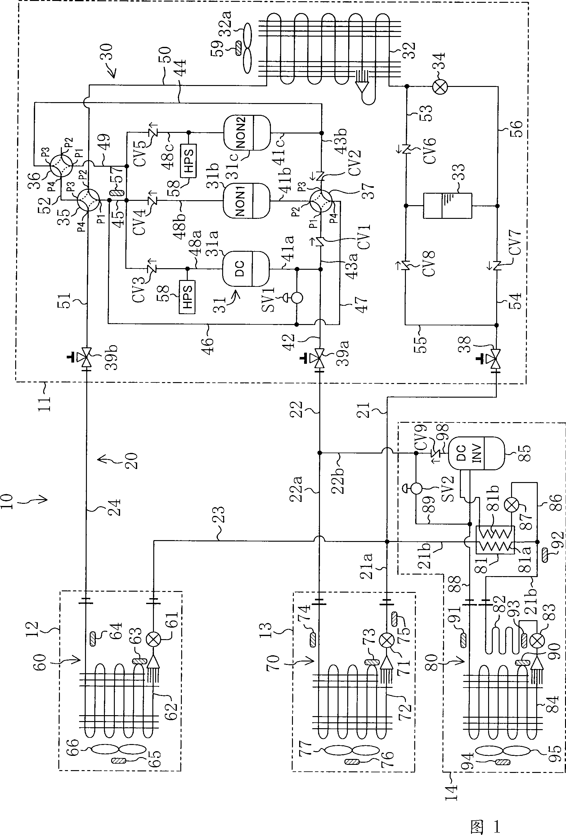
A first embodiment of the present invention will be described below. The refrigerating device (10) of the present embodiment is installed in the air-conditioning and cooling display cabinets used in convenience stores and the like.

[0061] As shown in Figure 1, the freezer (10) of present embodiment has outdoor unit (11), air-conditioning unit (12), as the refrigerated showcase (13) of refrigerator, and as the refrigerated showcase (14) of freezer . The outdoor unit (11) is arranged outdoors. On the other hand, the air-conditioning unit (12), the refrigerated display case (13) and the refrigerated display case (14) are all arranged in stores such as convenience stores.

[0062] Above-mentioned outdoor unit (11) is provided with outdoor circuit (30), is provided with air-conditioning circuit (air heat exchanger circuit) (60) at air-conditioning unit (12), is provided with refrigeration circuit (first cooling circuit) (70), and a freezing circuit (second cooling circuit) (8...

no. 1 example effect -

According to the refrigerating device (10) of the present embodiment, even if there is no defrosting mechanism such as an electric heater except the refrigerant circuit, both the refrigerating heat exchanger (72) and the refrigerating heat exchanger (84) can be defrosted, Therefore, it is possible to prevent the complexity of the device structure. In addition, not only defrosting both the refrigeration heat exchanger (72) and the freezing heat exchanger (84) can be performed simultaneously, but only one of them can be defrosted. Since defrosting can be performed on individual heat exchangers (72, 84) in this way, it is possible to cope with various defrosting operation patterns.

[0151] Furthermore, the existing refrigerating devices use the refrigerating heat exchanger as the heat source to defrost the refrigerating heat exchanger. During the defrosting operation, it is necessary to consider a good combination of the heat absorption and heat dissipation of the refrigerating ...

no. 2 example 》

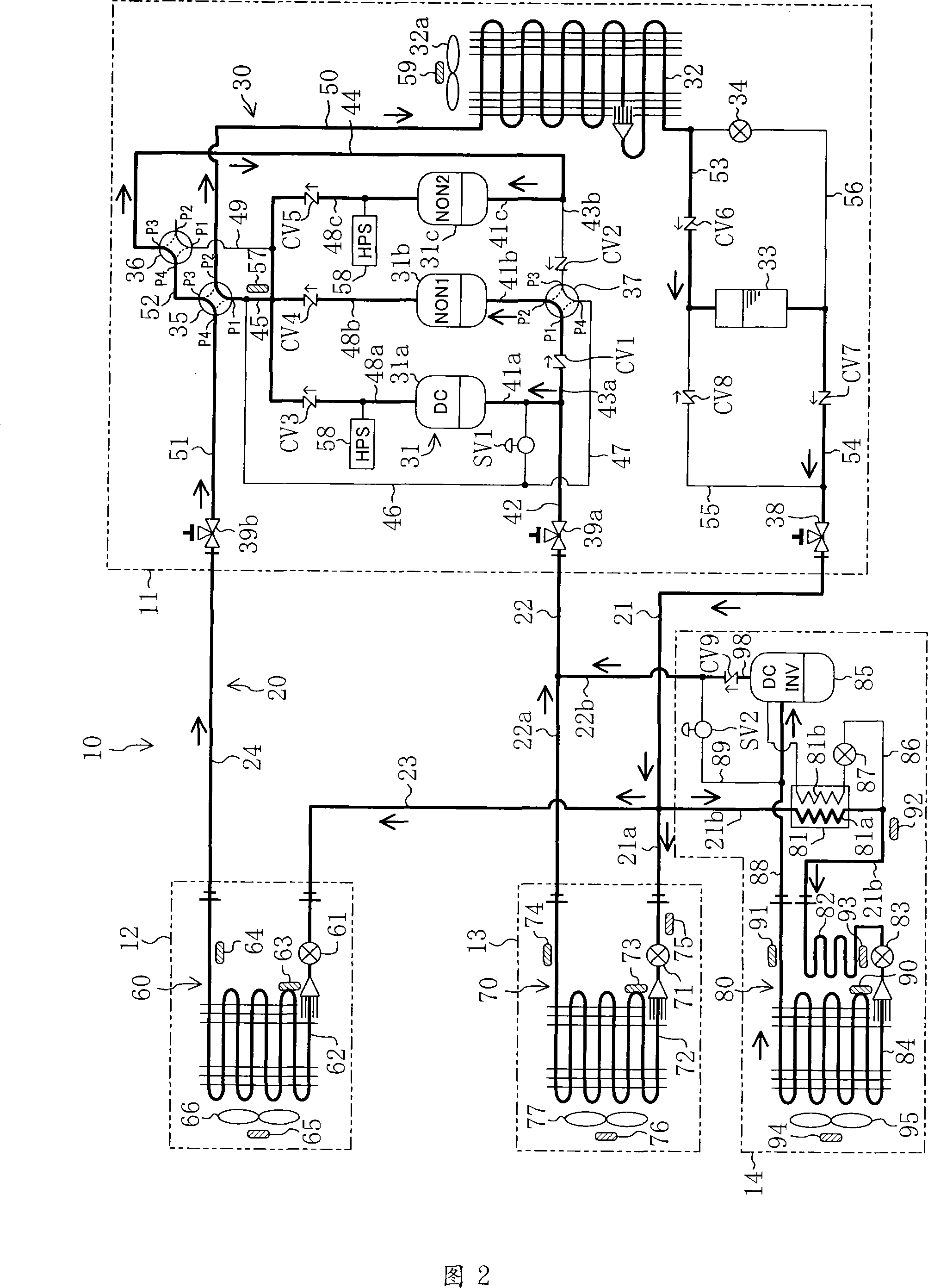
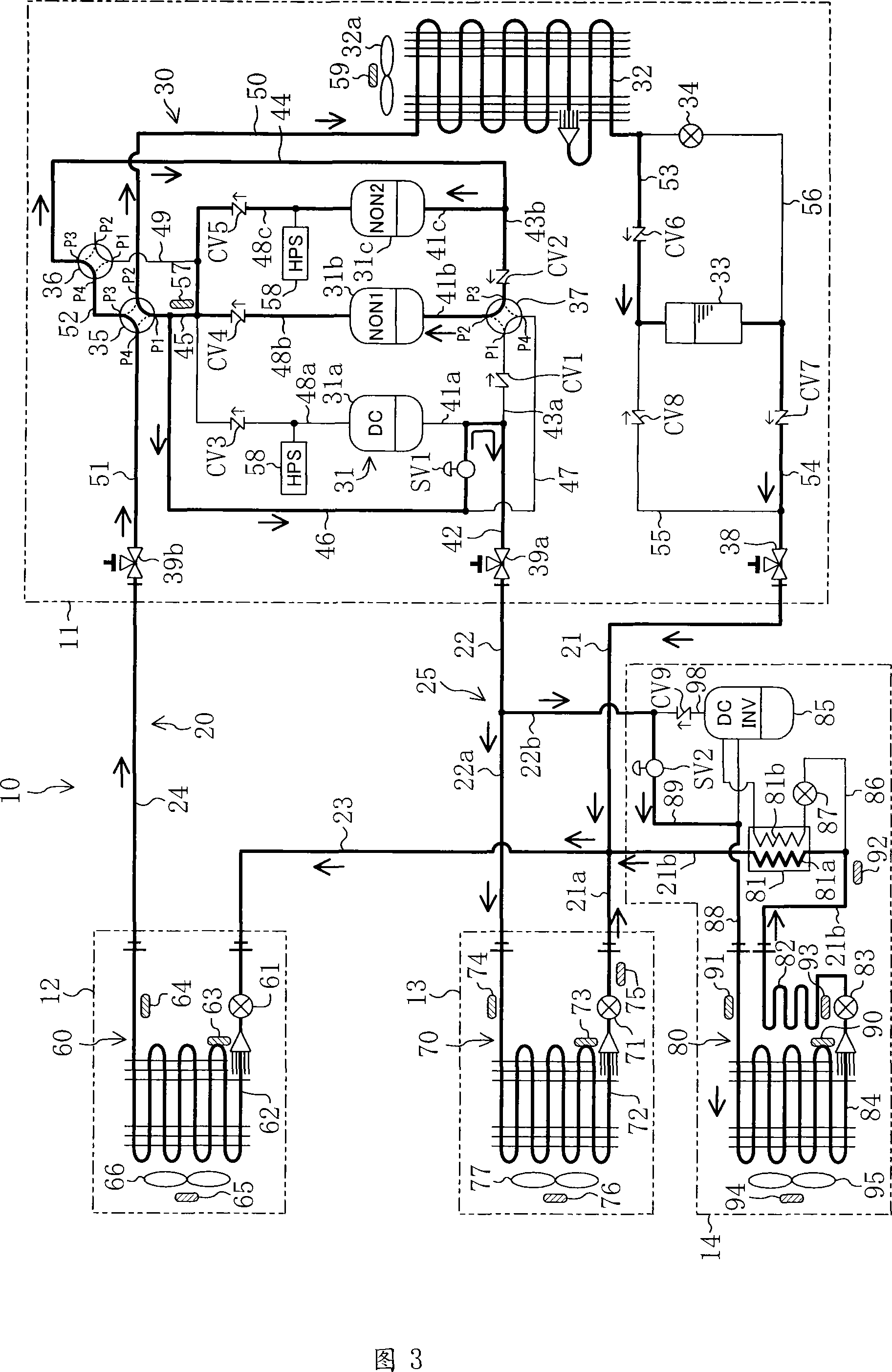
The freezing device (10) of the second embodiment, as shown in Fig. 8, differs from the first embodiment in the structure of a part of the outdoor unit (11). Specifically, the structure of the high-level side hot gas passage (46) is different from that of the first embodiment. In the second embodiment, one end of the hot gas introduction passage (46) is connected to the high-pressure air pipe (45), and the other end is connected to the fourth valve port (P4) of the third four-way reversing valve (37). Furthermore, in the first embodiment, the first communication pipe (43a) is provided with a check valve (CV1), but in the second embodiment, it is not provided.

[0158] Other structures are the same as the first embodiment.

[0159] -Operation action-

In the second embodiment, as in the first embodiment, it is possible to perform cooling operation and

In the heating operation, both or one of the refrigerating heat exchanger (72) and the freezing heat exchanger (84) can be ...


PUM


Abstract

A refrigeration device having a refrigerant circuit (20) of a vapor-compression refrigeration cycle where cooling circuit (70, 80) systems having cooling heat exchangers (72, 84), respectively, are parallelly connected to an outdoor circuit (30) having arranged in it an outdoor heat exchanger (32) and a compression mechanism (31). In at least one cooling circuit (70, 80) system, an auxiliary compressor (85) is connected in series to the cooling heat exchanger (84). In order for the refrigeration device to be able to cope with various defrost operation patterns without a defrost mechanism other than the refrigeration circuit (20), the device is provided with hot gas introduction paths (46, 89) for selectively introducing discharge gas refrigerant, discharged from the compression mechanism (31) of the outdoor circuit (30), to at least one of the cooling heat exchanger (72, 84). This enables defrost operation where a refrigeration cycle is operated using the cooling heat exchangers (72, 84) as condensers.

Description

technical field [0001] The present invention relates to a refrigerating device having a refrigerant circuit of a vapor compression refrigerating cycle. The cooling circuit of the system is constituted; in particular, it relates to a refrigeration device, and the refrigeration device is connected in series with a cooling heat exchanger and a sub-compressor in at least one cooling circuit of the system. Background technique [0002] Freezers that perform a refrigeration cycle have been known, and have been widely used as cooling devices for refrigerators and freezers (or refrigerated showcases or freezer showcases) for storing food and the like. For example, Patent Document 1 discloses a refrigeration device including a plurality of heat exchangers for cooling inside a refrigerator or the like. In this refrigerating apparatus, a refrigerating heat exchanger for cooling the inside of the refrigerating showcase serving as the refrigerator and a freezing heat exchanger for coo...

Claims


Application Information

Patent Timeline
IPC IPC(8): F25B29/00F25B47/02
Inventor 竹上雅章植野武夫近藤东谷本宪治小田吉成野村和秀中岛洋登
Owner DAIKIN IND LTD
Why Eureka
Try Eureka