Discharge purifying device
A technology of exhaust purification device and exhaust flow path, which is applied in exhaust device, exhaust treatment, noise reduction device, etc., can solve problems such as difficulty in purifying NOx
- Summary
- Abstract
- Description
- Claims
- Application Information
AI Technical Summary
Problems solved by technology
Method used
Image


Examples
Embodiment approach 1
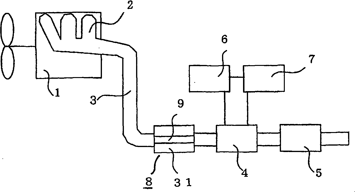
[0043] figure 1 It is a schematic diagram showing the basic configuration of the exhaust gas treatment device according to the first embodiment.
[0044] The engine 1 has a plurality of cylinders (not shown), and the exhaust gas combusted in the cylinders is discharged to the outside through a plurality of exhaust manifolds 2 and an exhaust pipe 3 .
[0045] In this exhaust treatment device, an oxidation catalyst unit 8 , a plasma treatment unit 4 , and a NOx purification catalyst unit 5 are provided in this order from upstream on an exhaust pipe 3 forming an exhaust flow path.
[0046] The oxidation catalyst unit 8 has a main passage 31 through which the exhaust gas flows in contact with the oxidation catalyst, and a bypass passage 9 formed at the center where the exhaust gas does not come into contact with the oxidation catalyst.
[0047] The plasma processing unit 4 is connected to a plasma control device 6 and a high voltage power supply 7 . The plasma control device 6 c...
Embodiment approach 2
[0082] Figure 4 It is a schematic diagram showing the basic configuration of the exhaust gas treatment device according to the second embodiment.
[0083] In this embodiment, the exhaust flow path formed by the exhaust pipe 3 has a main flow path 31 carrying an oxidation catalyst and a bypass flow path 9 not carrying an oxidation catalyst.
[0084] Other constitutions are the same as those in Embodiment 1.
[0085] In this embodiment, the piping forming the bypass flow path 9 is made of the same metal pipe as the exhaust pipe 3 .
[0086] The pipe diameter of the bypass passage 9 is determined by the concentration ratio of HC and NOx contained in the exhaust gas, the target concentration ratio, and the like.
[0087] Here, the main channel 31 loaded with the oxidation catalyst is a honeycomb structure, and the bypass channel 9 is a conduit structure. In addition to the diameters of the two, the numerical aperture is considered to determine the pipe diameter of the bypass ch...
Embodiment approach 3
[0094] FIG. 6 is a schematic diagram showing a basic configuration of an exhaust gas treatment device according to Embodiment 3. FIG.
[0095] In this embodiment, in the bypass channel 9 of Embodiment 2, a flow control device 10 is provided.
[0096] The other constitutions are the same as those of Embodiment 2.
[0097] In Embodiments 1 and 2, the sizes of the main flow path 31 and the bypass flow path 9 loaded with the oxidation catalyst are determined according to the concentrations of HC and NOx investigated in advance in the operating conditions of the engine 1, and the ratio of the exhaust gas is set.
[0098] On the contrary, in this embodiment, the bypass flow rate can be changed according to the operating conditions of the engine 1 through the control of the flow control device 10, thereby expanding the range of the operating conditions of the engine 1.
[0099] For example, when the air-fuel ratio of engine 1 is 20, the methane conversion concentration (C1 conversio...
PUM
 Abstract
Description
Claims
Application Information
 - R&D
- Intellectual Property
- Life Sciences
- Materials
- Tech Scout
- Unparalleled Data Quality
- Higher Quality Content
- 60% Fewer Hallucinations
Browse by: Latest US Patents, China's latest patents, Technical Efficacy Thesaurus, Application Domain, Technology Topic, Popular Technical Reports.
© 2025 PatSnap. All rights reserved.Legal|Privacy policy|Modern Slavery Act Transparency Statement|Sitemap|About US| Contact US: help@patsnap.com