

Fluid bearing device
A fluid bearing and bearing sleeve technology, applied in the field of fluid bearing devices, can solve the problem of limited improvement in machining accuracy, achieve the effects of realizing machining cost, avoiding reduction of coaxiality, and ensuring moment rigidity
Inactive Publication Date: 2010-11-10
NTN CORP
View PDF4 Cites 1 Cited by
- Summary
- Abstract
- Description
- Claims
- Application Information
AI Technical Summary
Problems solved by technology
Correspondingly, it is necessary to further process with high precision the inner peripheral surface of the bearing member forming the radial bearing gap and the outer peripheral surface of the shaft member. Difficult, in addition, there is a limit to improving machining accuracy in normal machining
Method used
View moreImage
Smart ImageViewing Examples

Examples
Embodiment Construction
Login to View More PUM
 Abstract
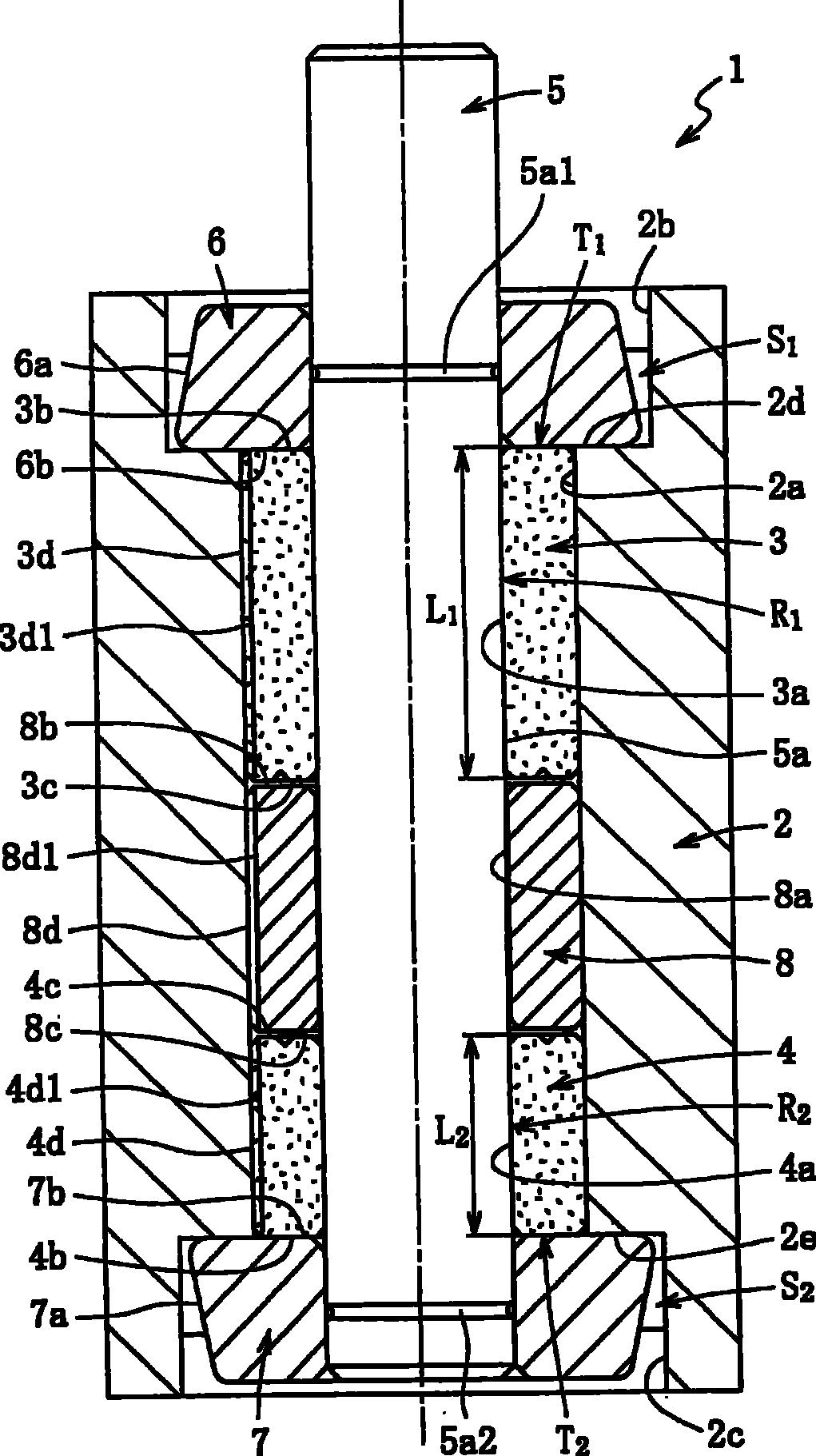
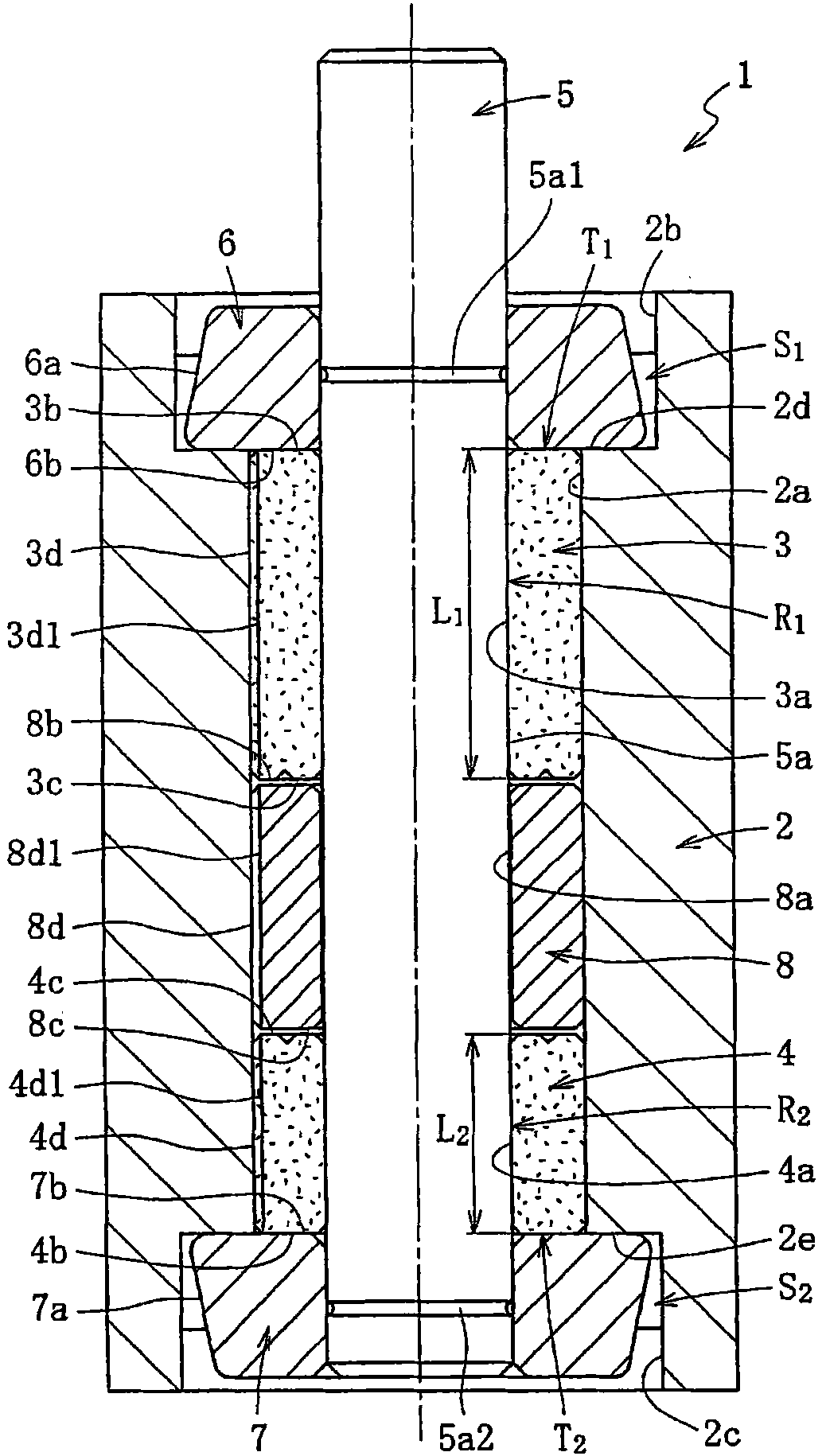
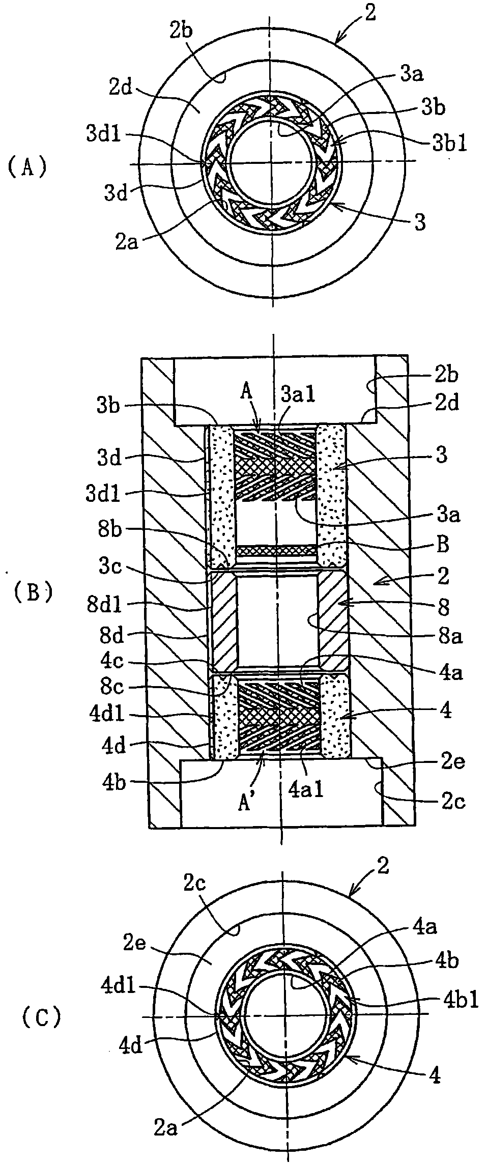
The present invention provides a fluid bearing device which has excellent moment rigidity and an improved working efficiency in assembling and parts control, and in which a bearing sleeve can be easily manufactured. A plurality of bearing sleeves are axially disposed in the fluid bearing device. The bearing sleeves (3, 4) are so formed that their axial lengths are different from each other.
Description
fluid bearing device technical field The invention relates to a fluid bearing device. Background technique In the fluid bearing device, the shaft member is rotatably supported by an oil film formed in a bearing gap. The fluid bearing has the characteristics of high-speed rotation, high rotation accuracy, and low noise. In recent years, its characteristics have been effectively used in information equipment such as HDD, FDD and other disk devices, CD-ROM, CD-R / RW, DVD-ROM / RAM It is widely used as a bearing for spindle motors on optical disc devices such as MD, MO, etc.; or as a bearing for fan motors mounted on personal computers (PCs) for heat source cooling. For example, in a fluid bearing device incorporated in a spindle motor of a disk drive device such as an HDD, both a radial bearing portion that supports the shaft member in the radial direction and a thrust bearing portion that supports the shaft member in the axial direction are sometimes composed of dynamic press...
Claims
Login to View More Application Information
Patent Timeline
 IPC IPC(8): F16C17/10F16C17/26H02K7/08
Inventor堀政治户田正明日比建治山本哲也
OwnerNTN CORP