Refrigerating container

A technology for refrigerated containers and containers, which is used in household refrigeration devices, coolers, refrigerators, etc., can solve the problems of inability to achieve compact refrigeration units and increase the diameter of fans, so as to improve the efficiency of oil supply operations and suppress the driving current. The effect of increasing and improving maintainability

Inactive Publication Date: 2009-08-05
YANMAR CO LTD
View PDF1 Cites 4 Cited by
  • Summary
  • Abstract
  • Description
  • Claims
  • Application Information

AI Technical Summary

Problems solved by technology

However, in this case, the rotation speed of the fan cannot reach the high-speed rotation of the evaporator fan, so the number of fans or the diameter of the fan increases.
In this way, the increase in the number of fans or the diameter of the fans is accompanied by an increase in the storage space, and the compactness of the refrigeration unit cannot be achieved.

Method used


Image

  • Refrigerating container
  • Refrigerating container
  • Refrigerating container

Examples


Embodiment Construction

[0073] Next, embodiments of the invention will be described.

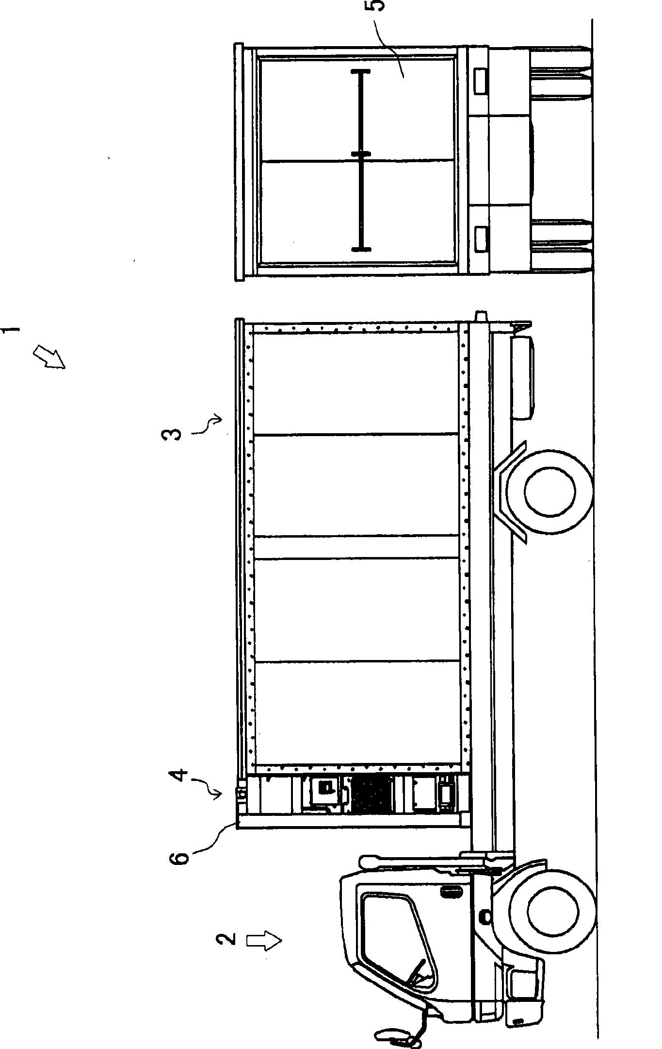
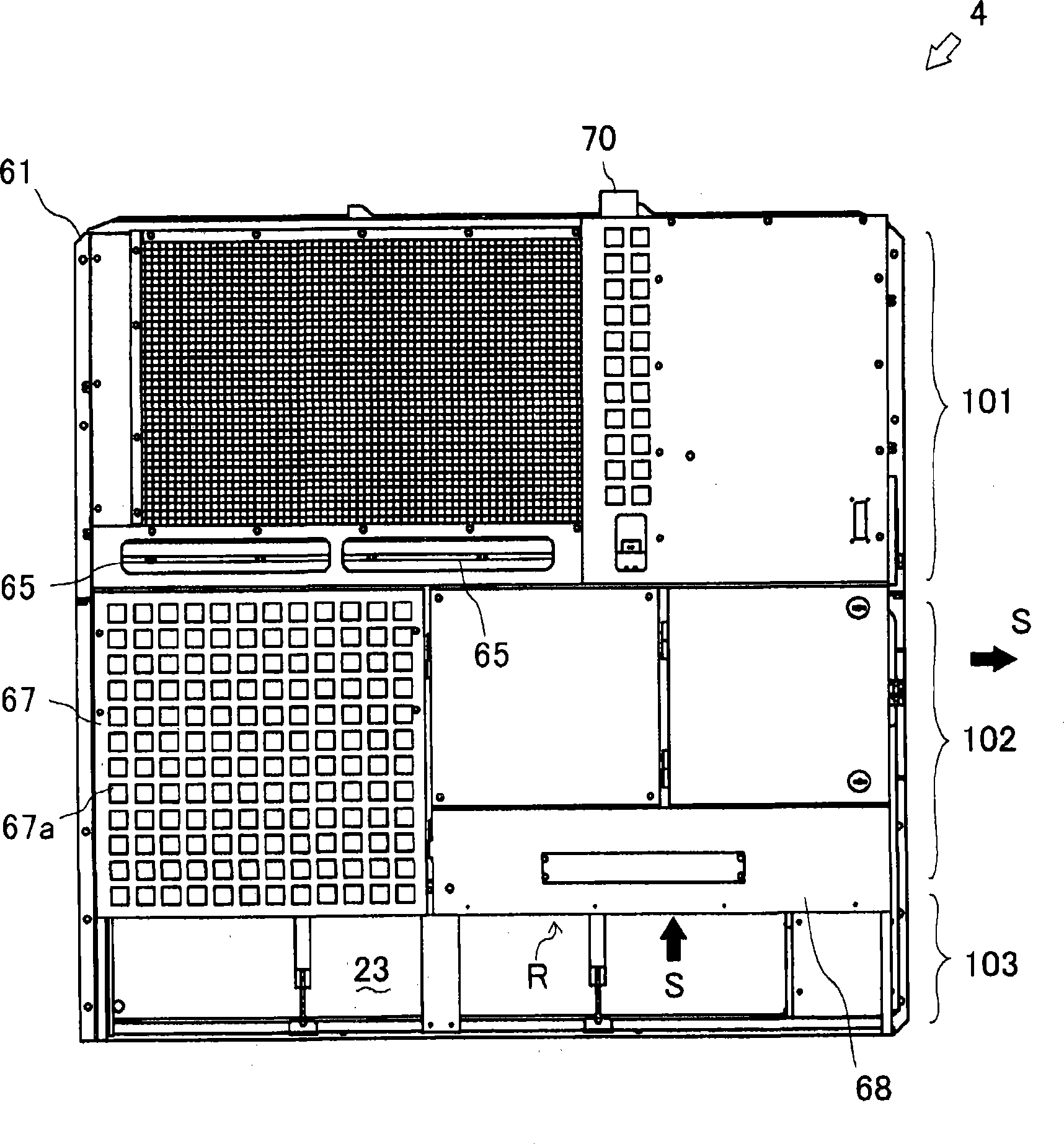
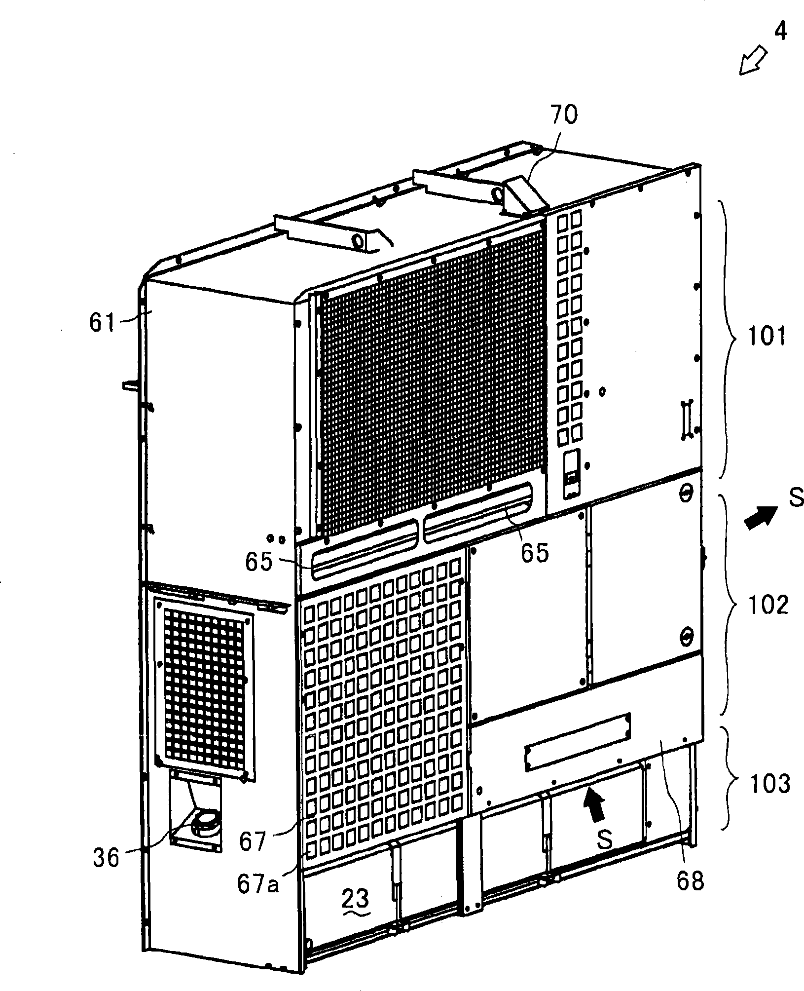
[0074] figure 1 It is a side view and a rear view showing the state where the refrigerated container of the present invention is loaded on a truck, figure 2 is the front view of the freezer unit, image 3 It is a perspective view seen from the front left of the freezing unit.

[0075] Figure 4 is a perspective view of the freezing unit seen from the front right, Figure 5 It is the front view of the state that removed the outer panel of the refrigeration unit, Figure 6 It is the rear view of the state which removed the outer panel of the refrigeration unit.

[0076] Figure 7 Indicates the configuration of the condenser and evaporator Figure 5 AA sectional view in, Figure 8 It means turning Figure 7 AA drawing of the state of the condenser fan bracket in, Figure 9 Indicates the composition of the exhaust tailpipe Figure 5 BB section view in .

[0077] Figure 10 Indicates the outlet structure o...


PUM


Abstract

A refrigerating container (1) in which the temperature in a container (3) is controlled by a refrigerating unit (4) in which a refrigerant is circulated by a compressor (11). One of the drive sources of the refrigerating unit (4) is an engine (22). To install a fuel tank (23) for the engine (22) into the refrigeration unit, the refrigerating unit (4) is divided into three parts arranged in the height direction. Heat exchangers of the refrigerating unit (4) and fans for them are disposed at the upper part (101), the engine (22) and a refrigerant device of the refrigerant unit (4) are disposed at the center part (102), and the fuel tank (23) is disposed at the lower part (103). Consequently, the entire devices including the engine and the fuel tank are efficiently arranged to realize efficient oil supply and maximized fuel tank capacity.

Description

technical field [0001] The present invention relates to the technology of the equipment arrangement structure of the refrigerated container. Background technique [0002] Conventionally, the technology of the refrigerated container which has a refrigerated unit on one end surface of the opening of a container is well-known. The refrigeration unit has equipment such as a compressor, an electronic component box, and a heat exchanger in one casing. In the refrigeration unit, the evaporator is arranged inside the container to exchange heat with the air in the container, and the condenser is arranged outside the container to exchange heat with the outside air. [0003] For example, Patent Document 1 in image 3 In, the layout structure of the heat exchangers of the refrigerating unit for refrigerated containers is disclosed. In the heat exchanger arrangement structure of Patent Document 1, the evaporator is arranged on the upper part of the housing, the condenser is arranged on...

Claims


Application Information

Patent Timeline
Patent Type & Authority Applications(China)
IPC IPC(8): F25D11/00F25D19/00F25B27/00
Inventor 山崎辰雄野口英明高桥洋介松冈功治佐藤孝康
Owner YANMAR CO LTD
Why Eureka
Try Eureka