Collector ring

A collector ring and conductive ring technology, applied in the field of collector rings, can solve the problems of long manufacturing process cycle, short effective creepage distance, brush dust accumulation on the surface, etc., achieve small wind resistance, increase creepage distance, The effect of shortening the production cycle

Active Publication Date: 2009-09-09
上海电气集团上海电机厂有限公司
View PDF0 Cites 5 Cited by
  • Summary
  • Abstract
  • Description
  • Claims
  • Application Information

AI Technical Summary

Problems solved by technology

[0002] The existing collector ring adopts the assembly process, and the insulating material in the middle is composed of mica board, glass gray cloth, etc., and the manufacturing process cycle is long
[0003] At the same time, the disadvantag

Method used


Image

  • Collector ring
  • Collector ring

Examples


Embodiment Construction

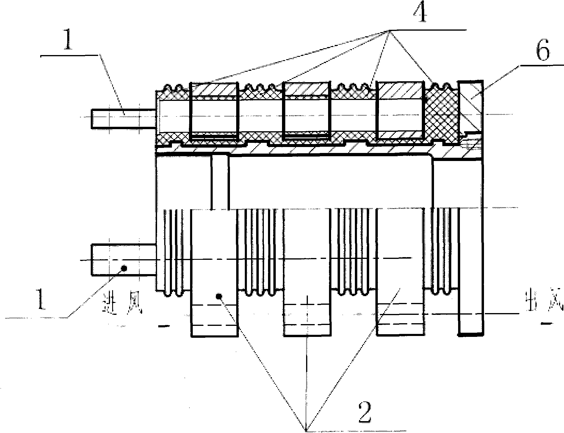
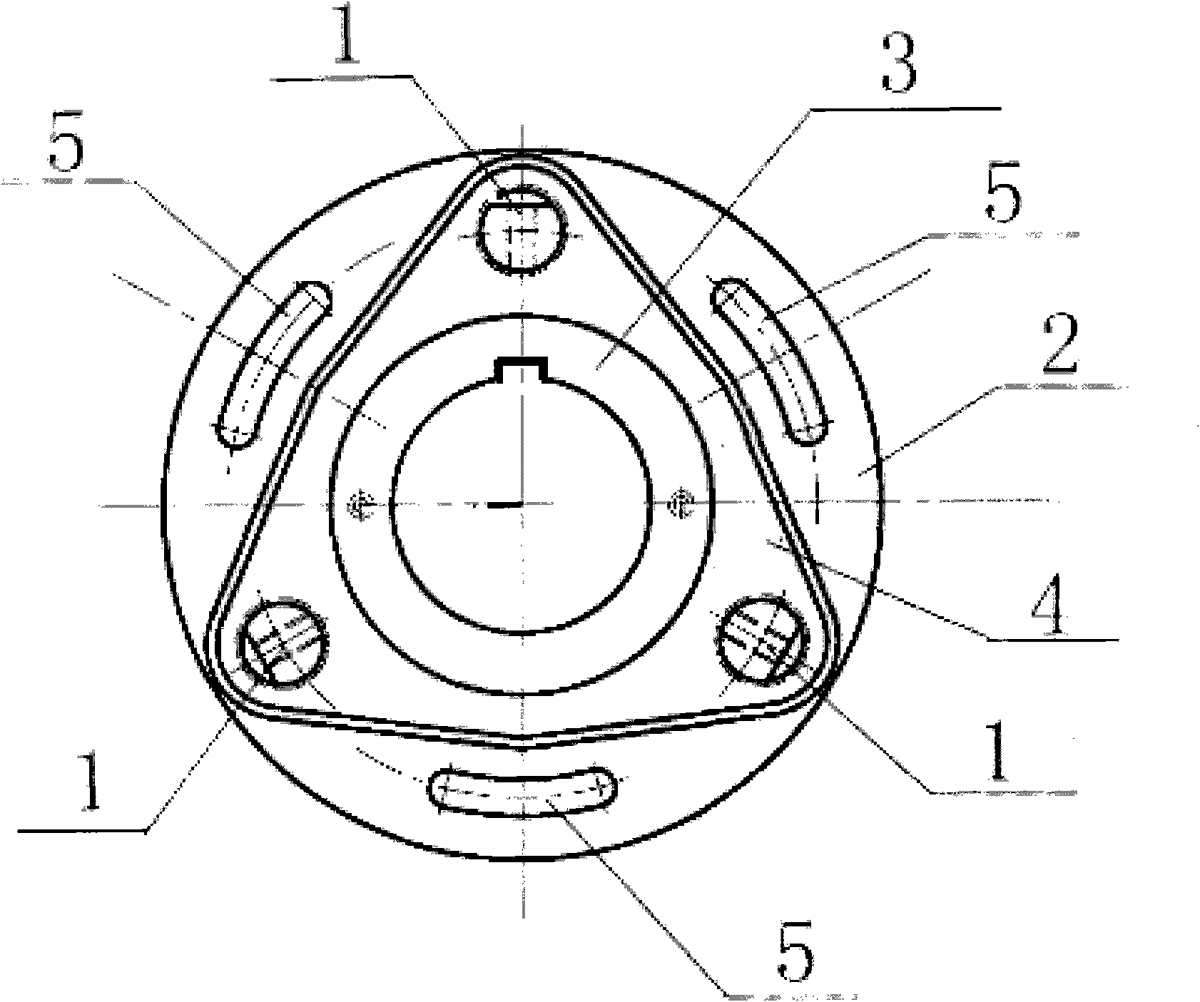
[0017] see figure 1 , figure 2 , figure 1 , figure 2 They are respectively the front view and side view cross-sectional structural schematic diagrams of a slip ring comprising three conductive rings of the present invention. The collector ring of the present invention includes 3 conductive rods 1, 3 conductive rings 2, 1 grounding slip ring 6 and 1 sleeve 3, and is characterized in that: between the 3 conductive rings 2 and between the grounding slip ring 6 There are spacer columns 4 made of mixed resins between them, the first conductive rod passes through one spacer bar and is connected with the corresponding first conductive ring, the second conductive rod passes through one conductive ring and two The spacer is connected to the corresponding second conductive ring, the third conductive rod passes through the two conductive rings and the three spacer bars, and is connected to the corresponding third conductive ring. The sleeve 3 is located in the center of the collecto...


PUM


Abstract

The invention relates to a collector ring, which comprises n conducting rods, n conducting rings, one grounded slip ring and one sleeve, and is characterized in that spacing columns made from mixed resin are arranged among the n conducting rings and between the conducting rings and the grounded slip ring, the nth conducting rod runs through n-1 conducting rings and n-1 spacing columns among the n-1 conducting rings and is connected with a corresponding nth conducting ring, the sleeve is positioned in the center of the collector ring and runs through the whole collector ring, and the conducting rings are provided with a plurality of annular equidistantly distributed circular orifices. The collector ring has good integrity, and small wind resistance and low noise under high-speed rotation; each conducting ring including the grounding ring has an axial air hole; in the overall design, an inside fan drives out worn electrical brush dust directly to reduce the inside dust accumulation; and the collector ring also increases the creepage distance.

Description

technical field [0001] The invention relates to a slip ring. Background technique [0002] The existing collector ring adopts an assembly process, and the insulating material is used in the middle, which is composed of mica board, glass gray cloth, etc., and the manufacturing process cycle is long. [0003] At the same time, the disadvantages of the existing collector rings are: the effective creepage distance is short, axial ventilation is impossible, and brush dust is likely to accumulate on the surface, which increases the probability of short-circuit firing. Contents of the invention [0004] The object of the present invention is to provide a slip ring in order to solve the above problems. [0005] The object of the present invention is achieved like this: the present invention provides a kind of collector ring, comprises n conductive rods, n conductive rings, 1 grounding slip ring and 1 sleeve, is characterized in that: between n conductive rings There is a spacer ...

Claims


Application Information

Patent Timeline
IPC IPC(8): H01R39/08H01R43/10
Inventor 吴家岐孙明伦朱燕
Owner 上海电气集团上海电机厂有限公司
Why Eureka
Try Eureka