Photomagnetically coded electronic tag, real-time equipment monitoring and engine frame positioning system and real-time equipment monitoring and engine frame positioning method

A technology of electronic tags and magnetic encoding, applied in radio wave measurement systems, electromagnetic radiation induction, computer components, etc., can solve the problems of increased cost and implementation difficulty, huge cost of manufacturing and installation, loss of real-time monitoring effect, etc., to achieve Perfect real-time monitoring and rack and shelf positioning function, extended service life, stable and reliable working performance

Inactive Publication Date: 2009-09-30
上海晶舜信息科技有限公司
View PDF0 Cites 13 Cited by
  • Summary
  • Abstract
  • Description
  • Claims
  • Application Information

AI Technical Summary

Problems solved by technology

[0008] The position of the active RFID electronic tag is mainly judged by the fixed-point distributed RFID reader. However, if the equipment enters the rack, the metal chassis will shield the signal sent by the tag and lose the effect of real-time monitoring. Therefore, some people use it in the rack. The method of installing a repeater at a certain position on the Internet greatly increases the cost and implementation difficulty of the entire system, and this method still cannot solve the problem of rack positioning
[0009] Although placing Hall or photoelectric sensors on the rack is still one of the main methods to solve the problem of rack positioning at present, each shelf position of the rack The way to install the sensor, its own manufacturing and installation are costly

Method used


Image

  • Photomagnetically coded electronic tag, real-time equipment monitoring and engine frame positioning system and real-time equipment monitoring and engine frame positioning method

Examples


Embodiment Construction

[0033] In order to understand the technical content of the present invention more clearly, the following examples are given in detail.

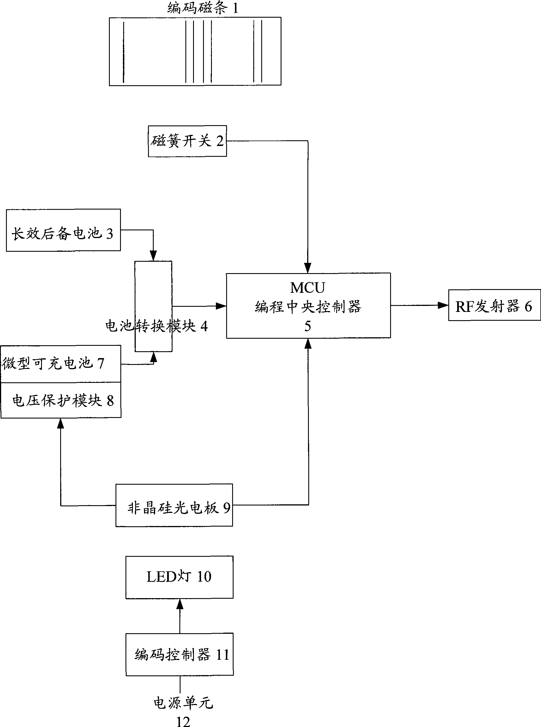
[0034] see figure 1 As shown, the optical-magnetic encoded electronic tag includes an RFID transmitter 6, an antenna, a central controller 5 and a power module, and the power module is connected to the antenna through the central controller 5 and the RFID transmitter 6 in turn , wherein, the electronic tag also includes a magnetic induction device 2 and an optical induction device 9, the magnetic induction device 2 and the optical induction device 9 are respectively connected to the central controller 5, and the power supply module includes a rechargeable battery unit, backup battery 3 and battery conversion unit 4, the light sensing device 9 is connected to the rechargeable battery unit, and the rechargeable battery unit and backup battery 3 are respectively connected to the battery conversion unit 4 The central controller 5 described above...


PUM


Abstract

The invention relates to a photomagnetically coded electronic tag, which comprises an RFID transmitter, an antenna, a central controller and a power module, wherein the power module is connected with the antenna through the central controller and the RFID transmitter. The photomagnetically coded electronic tag also comprises a magnetic induction device and a photoinduction device, wherein the magnetic induction device and the photoinduction device are connected with the central controller respectively; the power module comprises a rechargeable battery unit, a backup battery and a battery conversion unit; the photoinduction device is connected with the rechargeable battery unit; and the rechargeable battery unit and the backup battery are connected with the central controller through the battery conversion unit. The invention also relates to a real-time equipment monitoring and engine frame positioning system which comprises the electronic tag and a real-time equipment monitoring and engine frame positioning method. Due to adoption of the photomagnetically coded electronic tag, the real-time equipment monitoring and engine frame positioning system and the real-time equipment monitoring and engine frame positioning method, the invention greatly prolongs the service life of the electronic tag, realizes maintenance free in deed, realizes perfect real-time monitoring and engine frame positioning functions, not only has low cost but also has stable and reliable operating performances, and has wide application scope.

Description

technical field [0001] The present invention relates to the field of radio frequency identification and electronic communication, in particular to the technical field of real-time monitoring and positioning management of electronic tags and equipment, and specifically refers to a system and method for real-time monitoring of optical-magnetic coded electronic tags, equipment real-time monitoring and positioning of racks and shelves. Background technique [0002] In modern society, with the continuous development of social economy, how to carry out real-time asset monitoring and management has become an important issue before people. In the current existing technology, real-time asset monitoring and management is mainly realized by using RFID electronic tags. RFID electronic tags can be divided into two types: active and passive. [0003] For passive RFID electronic tags, its working principle is as follows: [0004] The electronic tag itself has no built-in power supply, and...

Claims


Application Information

Patent Timeline
Patent Type & Authority Applications(China)
IPC IPC(8): G06K19/07G06K7/10G01S13/74
Inventor 钟福兴
Owner 上海晶舜信息科技有限公司
Why Eureka
Try Eureka