LED lighting device

A technology of LED lighting and LED chips, which is applied to lighting devices, lighting device parts, lighting and heating equipment, etc., can solve the problems of limited lighting angle, insufficient lighting power, poor lighting effect, etc., and achieves compact structure, light-emitting The effect of increased power, good lighting effects

Inactive Publication Date: 2010-03-17
中山市中茗电器有限公司
View PDF0 Cites 0 Cited by
  • Summary
  • Abstract
  • Description
  • Claims
  • Application Information

AI Technical Summary

Problems solved by technology

The LED lighting device with this structure can only be installed with a single LED chip 103, and its luminous power is insufficient, and the lighting effect is not good. In addition, because the LED chip 103 is installed in the cup on the metal bracket 101, when the LED lighting device is powered

Method used


Image

  • LED lighting device
  • LED lighting device
  • LED lighting device

Examples


Embodiment Construction

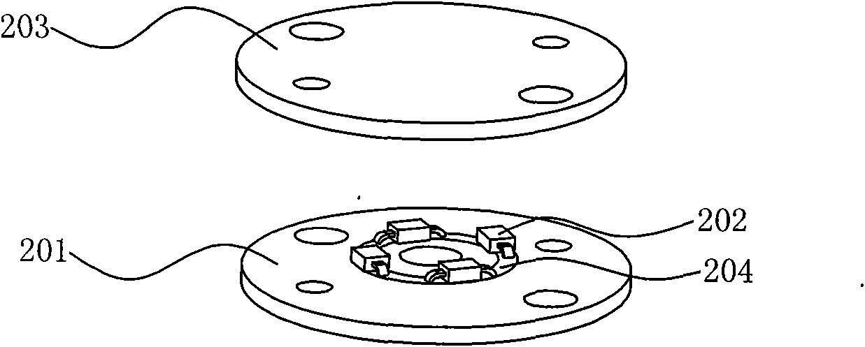
[0017] refer to figure 2 , an LED lighting device of the present invention, comprising a substrate 201 and at least one LED chip 202 fixedly mounted on the substrate 201, the substrate 201 is a flat sheet structure, the substrate 201 is provided with a pit 204, and the LED chip 202 is planted in the pit Inside the groove 204. In actual application, the positive pole and the negative pole of the power supply for providing DC power supply energy are provided on the side of the pit 204, and the electrodes of the LED chip 202 are respectively connected to the positive pole and the negative pole of the power supply. The LED lighting device using this power supply mode has multiple LED chips 202 can be placed into the pit 204 at the same time and the LED chips 202 do not interfere with each other. When multiple LED chips 202 are implanted in the pit 204, the luminous power of the LED lighting device is improved and has a better lighting effect.

[0018] In actual application, the ...


PUM


Abstract

The invention discloses an LED lighting device. The LED lighting device comprises a base plate and at least one LED chip which is fixedly arranged on the base plate, the base plate is of a flat sheetstructure and is provided with a slot, and the LED chip is embedded in the slot. The slot of the base plate can be embedded with adequate LED chips as required, and lighting power is improved and thelighting device has good lighting effect when a plurality of the LED chips are silmultaneously embedded into the slot. In addition, as the base plate is of the flat sheet structure, light given out bythe LED chips embedded in the slot is not blocked and has large enough lighting angle; and when a plurality of the LED chips are silmultaneously powered on, area light source is formed on the surfaceof the base plate, thus light given out by the lighting device is more even and lighting effect is better.

Description

technical field [0001] The invention relates to an illuminating device, in particular to an illuminating device using LED chips to emit light. Background technique [0002] Existing LED lighting devices generally adopt such as figure 1 In the shown structure, the LED chip 103 is fixed on the metal bracket 101 through the crystal bonding glue 102, and the two electrodes of the chip are respectively connected to the metal bracket 101 at both ends through the conductive wire 104, and the sealing resin 105 is coated on the surface of the LED chip 103. Further secure and protect. The LED lighting device with this structure can only be installed with a single LED chip 103, and its luminous power is insufficient, and the lighting effect is not good. In addition, because the LED chip 103 is installed in the cup on the metal bracket 101, when the LED lighting device is powered on, the LED The light emitted by the chip 103 to the side will be blocked by the cup body, and only the li...

Claims


Application Information

Patent Timeline
IPC IPC(8): F21S2/00F21V19/00F21V9/10F21Y101/02F21K9/238F21V9/40F21Y115/10
Inventor 钟继叶钟少乾
Owner 中山市中茗电器有限公司
Why Eureka
Try Eureka