Light emitting diode lamp

A technology of light-emitting diodes and lamps, which is applied to semiconductor devices, light sources, lampshades and other directions of light-emitting elements, can solve the problem of small irradiation range, and achieve the effects of improving heat dissipation efficiency and expanding the irradiation range.

Inactive Publication Date: 2010-07-07
FU ZHUN PRECISION IND SHENZHEN +1
View PDF0 Cites 7 Cited by
  • Summary
  • Abstract
  • Description
  • Claims
  • Application Information

AI Technical Summary

Problems solved by technology

[0003] Usually, the light-emitting diodes in the light-emitting diode lamps are distributed on a plane, and the entire lamp is a two-dimensional plane light source, and its irradiation range is small

Method used


Image

  • Light emitting diode lamp
  • Light emitting diode lamp
  • Light emitting diode lamp

Examples


Embodiment Construction

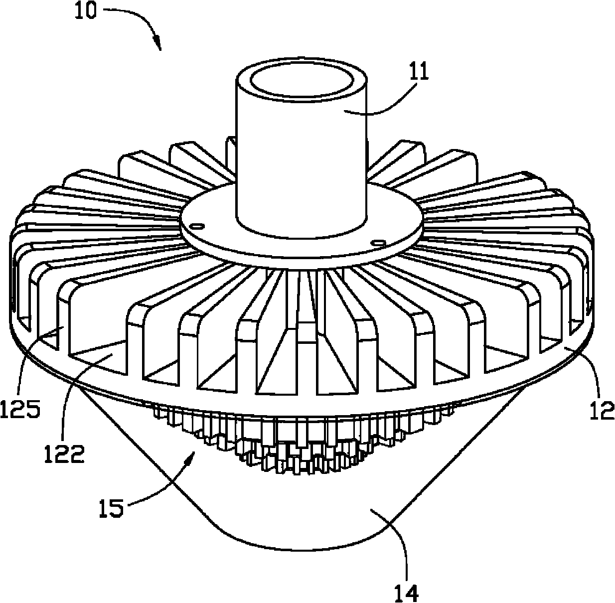
[0012] Such as figure 1 As shown, the LED lamp 10 includes a lamp post 11 , a lamp frame 12 , a light emitting module 15 and a transparent lampshade 14 . The lamp post 11 is located above the lamp frame 12 and serves as a suspension connection part of the LED lamp 10 . The transparent lampshade 14 is located below the lamp frame 12 and covers the outer edge of the lamp frame 12 . The lamp frame 12 and the transparent lampshade 14 jointly form a receiving space 141 for accommodating the light emitting module 15 .

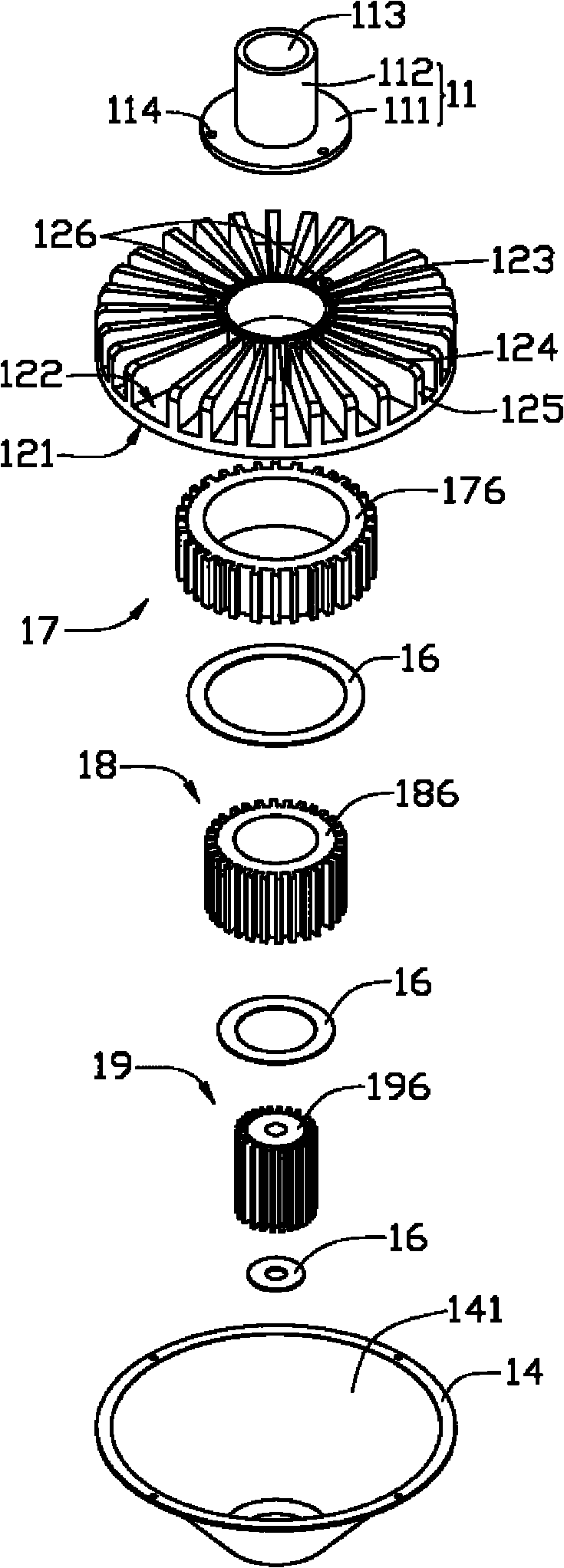
[0013] Please also refer to figure 2 The light pole 11 includes a base plate 111 and a connecting post 112 , the connecting post 112 extends upward from the center of the base plate 111 , and a receiving hole 113 is defined in the center of the connecting post 112 . The base plate 111 is provided with three installation holes 114 , and the three installation holes 114 are symmetrically distributed around the connecting posts 112 .

[0014] The lamp frame 12 is ma...


PUM


Abstract

The invention relates to a light emitting diode lamp comprising a lamp frame, a plurality of radiators that are fixed on the lamp frame in a sleeving way circle by circle from inside to outside, and a plurality of light emitting units. The plurality of light emitting units and the plurality of radiators are in one-to-one correspondence; each radiator comprises a mounting surface fixed to the lamp frame and a heat absorbing surface opposite to the mounting surface; each light emitting unit is arranged on the heat absorbing surface of the corresponding radiator; and the heat absorbing surface of the radiator in each inner circle is protruded out of the heat absorbing surface of the adjacent radiator in the outer circle along a direction away from the lamp frame. Compared with the prior art, the light emitting diode lamp light source is generally in an inverted cone solid shape so that the irradiation range of the whole light emitting diode lamp is enlarged; besides, each radiator can directly transmit heat produced by the corresponding light emitting unit on the lamp frame, thereby improving the radiating efficiency of each light emitting unit.

Description

technical field [0001] The invention relates to a lighting device, in particular to a light emitting diode lamp. Background technique [0002] As an emerging light source, light-emitting diode light source has many characteristics such as long working life, environmental protection, power saving, and long life. Moreover, the current modules composed of light-emitting diodes can produce high-power, high-brightness light sources, so they will widely and revolutionaryly replace existing light sources such as traditional incandescent lamps, and then become the main light source in line with the theme of energy conservation and environmental protection. [0003] Usually, the light emitting diodes in the light emitting diode lamp are distributed on a plane, and the whole lamp is a two-dimensional plane light source, and its irradiation range is small. Contents of the invention [0004] In view of this, it is necessary to provide a light-emitting diode lamp with a larger irradia...

Claims


Application Information

Patent Timeline
Patent Type & Authority Applications(China)
IPC IPC(8): F21V29/00H01L23/367F21Y101/02
CPCH01L2924/0002F21V21/116F21Y2111/008Y10S362/80F21Y2101/02F21V29/22F21V29/2231F21V29/2293F21K9/00F21Y2103/022F21Y2111/001F21V29/70F21V29/773F21V29/83F21Y2115/10F21Y2103/33F21Y2107/00F21Y2107/60F21V3/062F21V3/061H01L2924/00
Inventor 杨日朗余光
Owner FU ZHUN PRECISION IND SHENZHEN
Why Eureka
Try Eureka