Screwing and buckling clamp for connecting and disassembling drill rod and sleeve pipe

A technology of turnbuckle pliers and casing, which is applied in the direction of drill pipe, drill pipe, casing, etc., which can solve the problems of high labor intensity, inconvenient operation, and the trouble of aligning and tightening the two pipes, so as to reduce the labor intensity Effect

Inactive Publication Date: 2010-07-21
CHENGDU SHIWEI TECH CO LTD
View PDF6 Cites 10 Cited by
  • Summary
  • Abstract
  • Description
  • Claims
  • Application Information

AI Technical Summary

Problems solved by technology

In the process of taking over, most of the processes are manually operated, which is difficult, labor-intensive, and dangerous. Usually, it is necessary to connect the drill pipes in groups of 3 in the mouse hole, and then connect the newly connected drill pipes from small to small. Lift it out from the mouse hole by means of winches, wire cables and other equipment, move it to the upper end of the existing drill pipe in the well, adjust the newly connected drill pipe to the vertical direction to face the upper end of the existing drill pipe, and connect the newly connected drill pipe. The three connected drill pipes are butt-tightened with the existing drill pipes in the drilling to complete the growth of the drill pipes in the drilling. As above, when they are in the mouse hole, they need to be connected. For pipe connection in drilling, in the above process, due to the long and heavy drilling pipe itself, "moving", "position adjustment" and "butt tightening" are currently time-consuming, labor-intensive, labor-intensive, and labor-intensive. High risk, very inconvenient to operate
Especially in the process of connecting three pipes in the mouse hole, because the pipe in the mouse hole and the pipe that is lifted up to be connected will be inclined, it is troublesome to align the two pipes and tighten them tightly.

Method used


Image

  • Screwing and buckling clamp for connecting and disassembling drill rod and sleeve pipe
  • Screwing and buckling clamp for connecting and disassembling drill rod and sleeve pipe
  • Screwing and buckling clamp for connecting and disassembling drill rod and sleeve pipe

Examples


Embodiment Construction

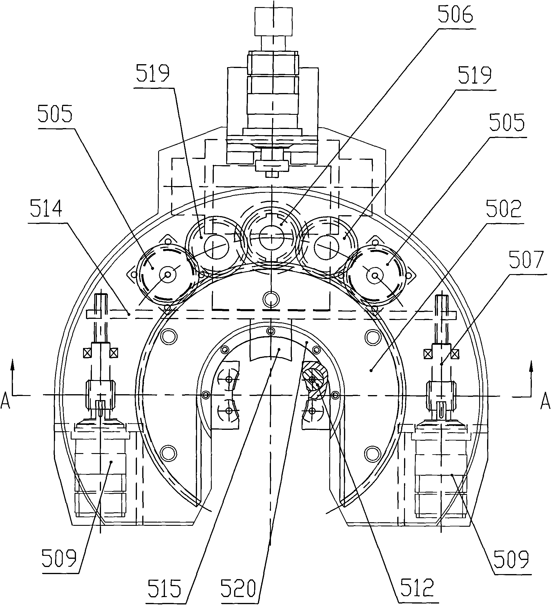
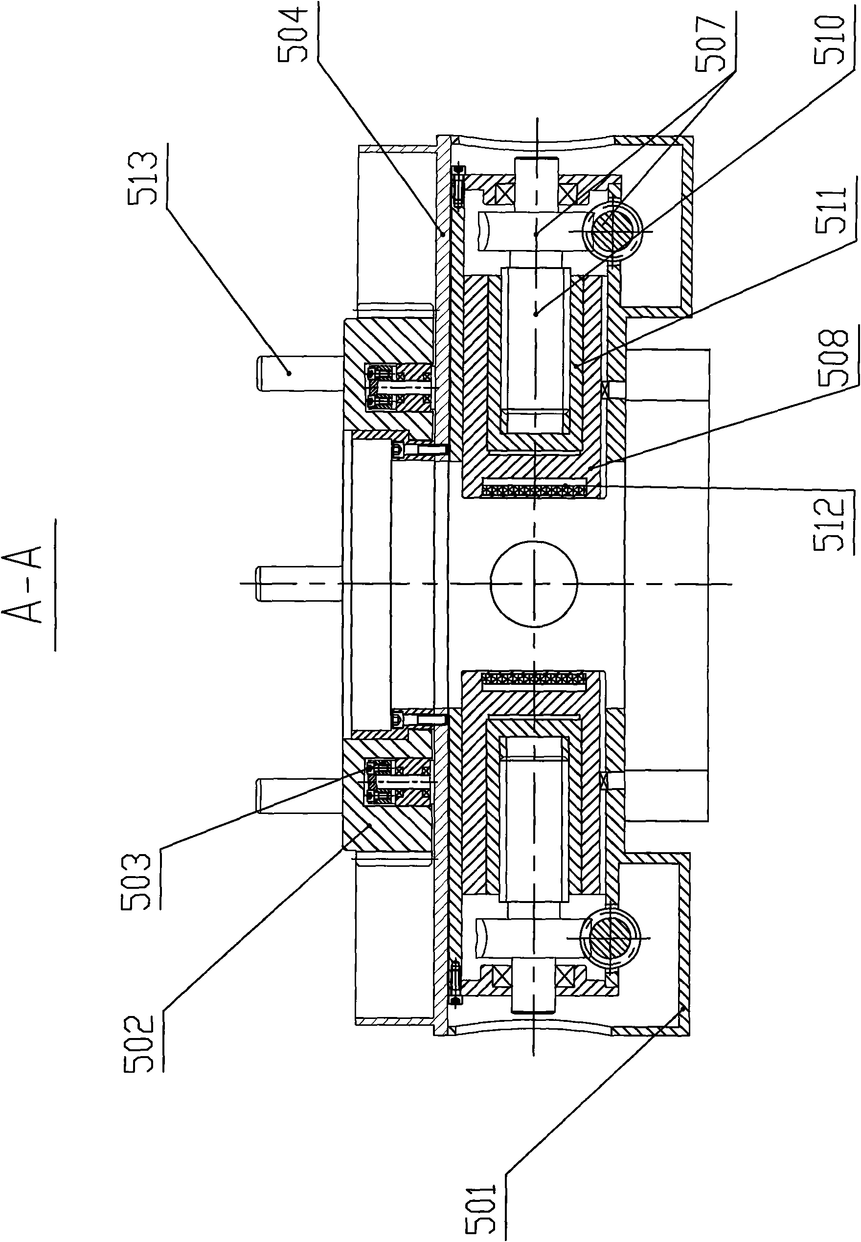
[0028] Such as figure 1 , 2 , 4 and 5: the fixed pliers include a fixed pliers housing 501, a large ring gear 502 with an opening and a large ring gear seat 503, and the large ring gear seat 503 is arranged above the fixed pliers housing 501 On the support plate 504 of the large ring gear 502, the lower part of the large ring gear 502 has an annular groove, and the upper surface is provided with a positioning pin 513, through which the large ring gear 502 is set on the large ring gear seat 503 and the large ring gear 502 can rotate relative to the large ring gear seat 503; the large ring gear driving gear 505 and the fastening gear 506 are also arranged on the support plate 504, and the large ring gear driving gear 505 and the fastening gear 506 are connected with an independent oil motor and The large ring gear driving gear 505, the fastening gear 506 and the outer ring of the large ring gear 502 mesh in pairs; the fixed pliers housing 501 below the support plate 504 is prov...


PUM


Abstract

The invention discloses a screwing and buckling clamp for connecting and disassembling a drill rod and a sleeve pipe, which comprises a power clamp and a fixing clamp, wherein the power clamp and the fixing clamp can rotate relatively; a driving oil motor sliding seat is also arranged on a shell of the fixing clamp; a latch driving oil motor supporting plate is arranged on the driving oil motor sliding seat; a latch driving oil motor is arranged on the latch driving oil motor supporting plate; a power output connector of the latch driving oil motor corresponds to an input connector of a power transmission shaft in the power clamp; a supporting plate pushing oil cylinder is arranged on the driving oil motor sliding seat; and the pushing end of the supporting plate pushing oil cylinder is connected with the latch driving oil motor supporting plate. By the design of the screwing and buckling clamp in the scheme, the structure can accurately and quickly complete screwed connection of drill pipes, and the pipe connecting process is stable and quick, thereby improving the pipe connecting efficiency, reducing the labor intensity and the risk of workers.

Description

technical field [0001] The invention belongs to the field of oil drilling equipment, and in particular relates to a spinner pliers for connecting and unloading drill pipes and casing pipes. Background technique [0002] With the development of the national economy, the demand for oil and natural gas is increasing, which requires that the speed and efficiency of exploration and development need to be improved. A new drill pipe is added to the drill pipe, commonly known as "takeover". In the process of taking over, most of the processes are manually operated, which is difficult, labor-intensive, and dangerous. Usually, it is necessary to connect the drill pipes in groups of 3 in the mouse hole, and then connect the newly connected drill pipes from small to small. Lift it out from the mouse hole by means of winches, wire cables and other equipment, move it to the upper end of the existing drill pipe in the well, adjust the newly connected drill pipe to the vertical direction t...

Claims


Application Information

Patent Timeline
Patent Type & Authority Applications(China)
IPC IPC(8): E21B19/18
Inventor 黄可唯李斌刘春全李阳
Owner CHENGDU SHIWEI TECH CO LTD
Why Eureka
Try Eureka