Sealed leakage-resistant thermal couple (resistor)

A thermocouple and leak-proof technology, which is applied in the direction of thermometers that are directly sensitive to heat/magnetic elements, measuring heat, and using electrical devices, etc., can solve the problem of non-adjustable length of measuring elements, no sealing leak-proof device, and maintenance High cost and other problems, to achieve the effect of simple structure, convenient operation and long service life

Inactive Publication Date: 2010-08-18
TIANJINSHI ZHONGHUAN TEMPERATURE METERS
View PDF0 Cites 8 Cited by
  • Summary
  • Abstract
  • Description
  • Claims
  • Application Information

AI Technical Summary

Problems solved by technology

[0002] Thermocouple (resistance) is one of the commonly used temperature sensors. The structure of armored thermocouple (resistance) commonly used in industrial sites is mainly composed of junction box, protective sleeve and temperature measuring element. ) The internal temperature measuring element is directly led from the junction box to the measuring point at the front end of the protective casing. This traditional structure has the following problems: 1. There is no sealing leak-proof device inside. Once the casing and the temperature measuring element are damaged, high temperature or Strong corrosive media will directly enter the junction box, which poses a great safety hazard; 2. The length of the measuring element cannot be adjusted. Once the design length does not match the actual length, it cannot be adjusted, resulting in the measured temperature and the actual one. 3. Once the thermocouple (resistance) is damaged, it can only be replaced as a whole, resulting in high maintenance costs

Method used


Image

  • Sealed leakage-resistant thermal couple (resistor)
  • Sealed leakage-resistant thermal couple (resistor)

Examples


Embodiment Construction

[0015] The present invention will be further described in detail below through the specific examples, the following examples are only descriptive, not restrictive, and cannot limit the protection scope of the present invention with this.

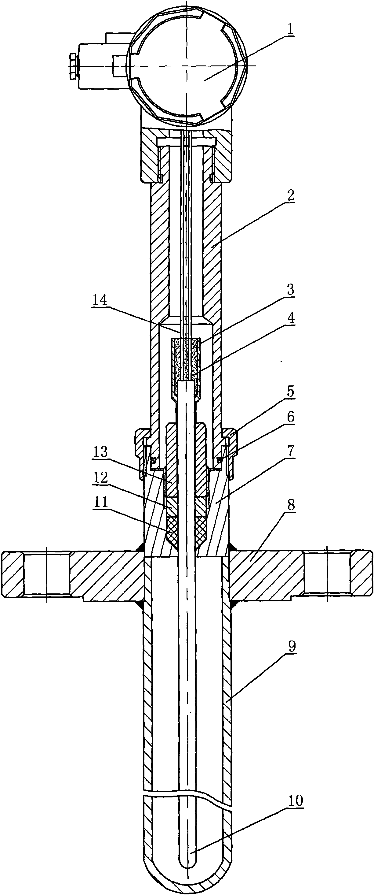
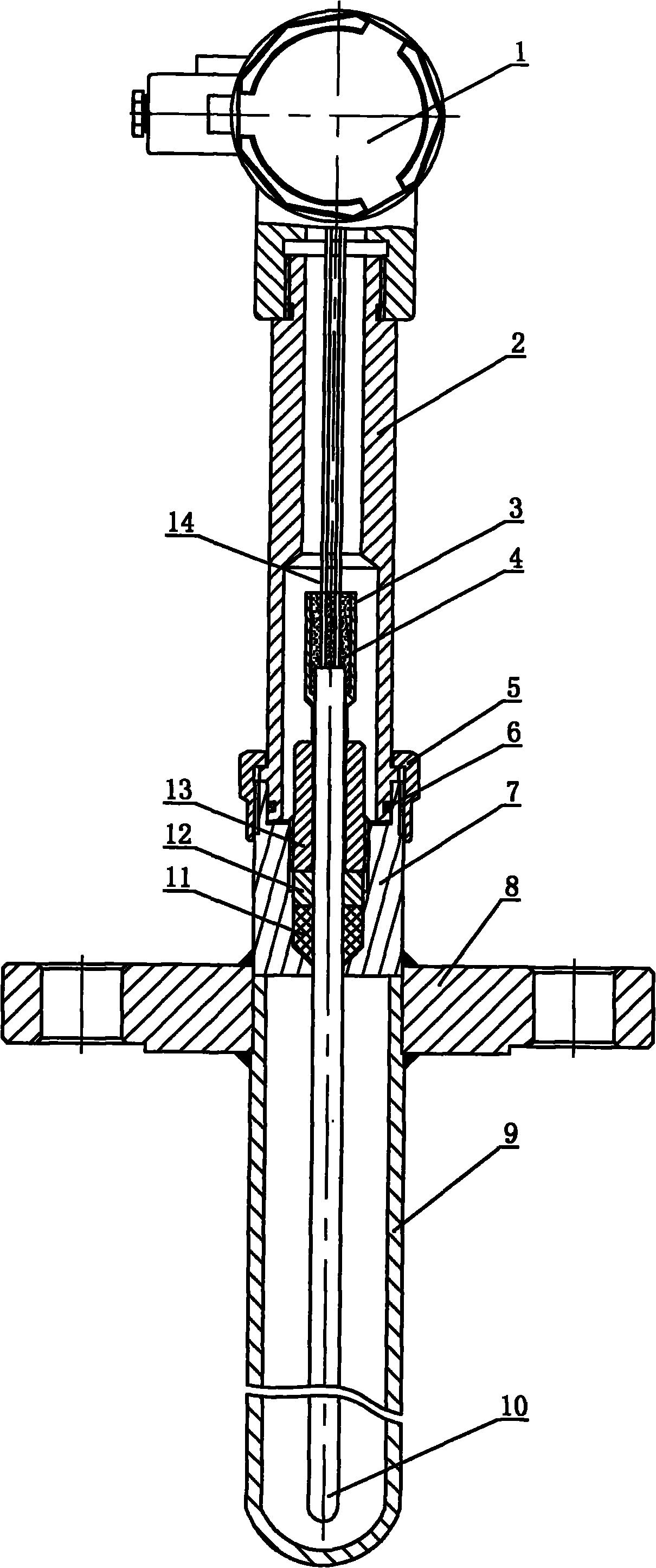
[0016] A sealed leak-proof thermocouple (resistance), which is composed of a junction box 1, a protective sleeve and a temperature measuring element 10. The protective sleeve is coaxially installed by an upper protective sleeve 2 and a lower protective sleeve 9. , the upper end of the upper protective casing is fixed on the junction box, the connecting wire 14 of the temperature measuring element is fixed on the junction box and placed in the protective casing, and a connecting flange 8 is fixed on the lower protective casing, wherein the upper protection A leak-proof seal seat 7 is fixed coaxially between the casing and the lower protective sleeve, the upper end of the leak-proof seal seat is coaxially installed with the upper protective sle...


PUM


Abstract

The invention belongs to a sealed leakage-resistant thermal couple (resistor), which consists of a junction box, a protection sleeve and a temperature measuring element. The protection sleeve consists of an upper protection sleeve and a lower protection sleeve which are arranged coaxially up and down. The upper end of the upper protection sleeve is fixedly arranged on the junction box; the temperature measuring element is coaxially arranged in the protection sleeve and the upper end of the temperature measuring element is fixedly arranged on the junction box. A leakage-resistant sealing base is fixedly arranged between the upper protection sleeve and the lower protection sleeve coaxially. The upper protection sleeve is coaxially arranged at the upper end of the leakage-resistant sealing base through a movable nut; the lower protection sleeve is fixedly arranged at the lower end of the leakage-resistant sealing base coaxially; and a pressing leakage-resistant device for the temperature measuring element is arranged on the leakage-resistant sealing base. The sealed leakage-resistant thermal couple (resistor) has the advantages of simple structure, scientific and reasonable design, adjustable length of the temperature measuring element of the thermal couple (resistor), separate replacement of the temperature measuring element, higher sealing safety, convenient operation, and long service life.

Description

technical field [0001] The invention belongs to the thermocouple (resistance) in the field of temperature sensors, in particular to a sealed leak-proof type thermocouple (resistance). Background technique [0002] Thermocouple (resistance) is one of the commonly used temperature sensors. The structure of armored thermocouple (resistance) commonly used in industrial sites is mainly composed of junction box, protective sleeve and temperature measuring element. ) The internal temperature measuring element is directly led from the junction box to the measuring point at the front end of the protective casing. This traditional structure has the following problems: 1. There is no sealing leak-proof device inside. Once the casing and the temperature measuring element are damaged, high temperature or Strong corrosive media will directly enter the junction box, which poses a great safety hazard; 2. The length of the measuring element cannot be adjusted. Once the design length does not...

Claims


Application Information

Patent Timeline
Patent Type & Authority Applications(China)
IPC IPC(8): G01K7/02G01K1/08
Inventor 刘汉杰
Owner TIANJINSHI ZHONGHUAN TEMPERATURE METERS
Why Eureka
Try Eureka