Method and system for detecting moving object

A moving target and distance map technology, applied in the field of moving target detection, can solve the problems of shortened effective monitoring distance, high cost, and inability to detect non-radiating signals

Inactive Publication Date: 2010-09-08
成都神州数码索贝科技有限公司
View PDF5 Cites 43 Cited by
  • Summary
  • Abstract
  • Description
  • Claims
  • Application Information

AI Technical Summary

Problems solved by technology

This is because, on the one hand, the effective monitoring distance of laser or CCD sensors based on vision will be greatly shortened under such conditions, and cannot provide effective confirmation information for radar sensors, while sensors based on infrared can only detect thermal signals. It is impossible to achieve effective detection of non-heat dissipation signals in the scene; on the other hand, this method is relatively expensive, and the expensive hardware cost also limits its wide application in practice

Method used


Image

  • Method and system for detecting moving object
  • Method and system for detecting moving object
  • Method and system for detecting moving object

Examples


Embodiment 1

[0079] The first embodiment is a moving target detection system, including:

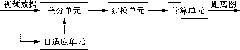
[0080] The distance map acquisition module is used to perform inter-frame difference on the input video image data to obtain a frame difference image, and establish a background model based on the frame difference image to obtain a background image; compare the current frame image and the background image to obtain a distance map;

[0081] The full image enhancement module is used to increase the pixel value difference between the moving target pixel and the noise pixel on the distance map to obtain the enhanced distance map of the full image; it is possible but not limited to use linear enhancement algorithm to increase the Narrative gap

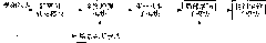
[0082] The detection module is used to determine the circumscribed rectangle of the moving target in the current frame image according to the distance map after the full image is enhanced.

[0083] In this embodiment, as figure 1 As shown, the detection module may specif...

Embodiment 2

[0156] The second embodiment is a moving target detection method suitable for very low contrast scenes, including:

[0157] Perform inter-frame difference on the input video image data to obtain a frame difference image, establish a background model based on the frame difference image, and obtain a background image; compare the current frame image and the background image to obtain a distance map;

[0158] Increasing the difference in pixel values ​​between the pixel points of the moving target and the noise pixel points on the distance map to obtain an enhanced distance map of the whole image;

[0159] Determine the circumscribed rectangle of the moving target in the current frame image according to the distance map after the full image is enhanced.

[0160] In this embodiment, the step of performing inter-frame difference on input video image data to obtain a frame difference image may specifically include:

[0161] Read in the data of each image frame sequentially; compare the simila...


PUM


Abstract

The invention discloses a system for detecting a moving object, which comprises a distance map acquisition module, a total map enhancement module and a detection module; wherein the distance map acquisition module is used to carry out inter-frame differentiation to the input video image data and to build up a background module according to the frame differentiated image to obtain a background image; the current image and the background image are compared to obtain a distance map; the total map enhancement module is used to increase the disparity of the pixel values of the pixel point of the moving object and the noise pixel point on the distance map to obtain a totally enhanced distance map; and the detection module is used to determine the enclosing rectangle of the moving object in thecurrent image according to the totally enhanced distance map. The system improves the stability of the background module and enables the background module to be free from the influence of the moving object at the current scene, and the system is suitable for the detection of moving objects at very low contrast.

Description

Technical field [0001] The invention relates to the field of moving target detection, in particular to a moving target detection method and system. Background technique [0002] In recent years, video surveillance technology has been increasingly used in the security field. With the continuous increase in the amount of surveillance data, surveillance personnel need to spend a lot of time to manually filter the data and select useful video information from it. Repeated work often makes them unable to do what they want. Monitoring personnel urgently need a product that is easier to work, easier to operate and manage to replace the original system. Thus, smart video technology came into being and entered people's lives. [0003] Intelligent Video (IV, Intelligent Video) is the introduction of computer vision (CV, Computer Vision) methods into video surveillance. This technology includes automatic detection of moving targets, target tracking, target classification and behavior under...

Claims


Application Information

Patent Timeline
Patent Type & Authority Applications(China)
IPC IPC(8): H04N5/14
Inventor 蒋敏潘巧海任楠楠章日康
Owner 成都神州数码索贝科技有限公司
Why Eureka
Try Eureka